background image

3

Index

Contents

Cutting Plotter Controller

OPS664

2  USING THE CONTROLLER

2.1  Launching the Controller

There are two ways of launching the Controller, either from the Windows Start menu or 
from the Print menu. Select either "Launch from the Start menu" or "Launch from the 
Print menu".
(1)  First of all, use the CD-ROM provided with your cutting plotter to set up your 

cutting plotter. 

Note: For details on how to perform setup, please refer to the Quick Start Manual.

(2)  Connect the cutting plotter to your computer via the USB connection, and load a 

medium.

(3)  Launch the Controller.


Using the Start menu to launch the Controller 

The Cutting Plotter Controller can be launched from the Windows Start menu.  
The registered location is: [Start]   [All Programs]   [Graphtec Cutting Plotter 
Controller]   [Cutting Plotter Controller]. 

Note: If the Controller is launched from the Start menu, only the test cutting and cross-

cutting operations can be performed.


Using the Print menu to launch the Controller


If you use the driver to send a print job from the application to the cutting 
plotter, the driver will automatically launch the Cutting Plotter Controller. 
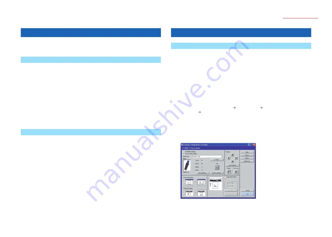
The following window is displayed when the Controller has been launched.

Note: If the Controller is launched from the Start menu, a [Close] button replaces the 

[Cancel] and [Cut] buttons.

Note: The screen above is the screen that is displayed when an FC7000 Series cutting 

plotter has been connected.

1  INTRODUCTION

The Cutting Plotter Controller is automatically installed when you perform setup for 
your cutting plotter in a Windows 2000/Windows XP or Windows Vista environment.

1.1  About the Controller

The Cutting Plotter Controller is a software program that lets you perform settings 
at your computer instead of having to make them at the plotter's control panel. In 
particular, frequently-used cutting condition settings and complicated registration mark 
reading procedures can be easily performed. Using the Controller together with the 
driver further improves overall operating efficiency.

Note:  The Cutting Plotter Controller was designed on the premise that it would be used for 

cutting text, print & cut applications, and so forth. It is not suitable for manufacturing-

industry purposes such as outputting multiple cutting conditions in a single cutting 

output operation.

Note:  The Cutting Master 2 plug-in provided with your cutting plotter has the same 

functions as this Controller. Moreover, since the plug-in enables data created in 

Illustrator/Corel Draw to be sent directly to the plotter for output, even more intuitive 

operation is enabled. If you are outputting data from Illustrator/Corel Draw, we 

recommend that you use the plug-in instead of this Controller.

1.2  Operating Environment

The minimum system requirements to enable operation of this software are as follows:

• OS: Windows 2000/Windows XP or Windows Vista 
• CPU: Pentium III 600 MHz or better 
• Memory: 128 MB minimum (256 MB recommended) 
• Monitor: Must be capable of 1024 x 768 High Color display (True Color 

recommended)

• Mouse
• CD-ROM drive
• Craft ROBOPro2, Craft ROBOPro, CE5000, FC7000
• USB connection

Note:  The Cutting Plotter Controller will not operate if it is connected via a printer or serial 

port.

Summary of Contents for OPS664

Page 1: ...ODUCTION 1 1 About the Controller 3 1 2 Operating Environment 3 2 USING THE CONTROLLER 2 1 Launching the Controller 3 2 2 Setting the Various Parameters 4 2 3 Edit Condition List 6 2 4 Cutting Conditions 7 2 5 Registration Mark Settings 8 2 6 Advanced Settings 9 3 ERROR MESSAGES 10 Index 11 USER S MANUAL MANUAL NO OPS664 UM 153 ...

Page 2: ...ftware and accompanying documentation Neither Graphtec nor the supplier gives any explicit or implicit guarantees regarding the infringement of a third party s rights arising from the use of the Software or accompanying manuals their commercial performance or their suitability for specific purposes Neither Graphtec nor the supplier assumes any responsibility for incidental secondary or special dam...

Page 3: ...led when you perform setup for your cutting plotter in a Windows 2000 Windows XP or Windows Vista environment 1 1 About the Controller The Cutting Plotter Controller is a software program that lets you perform settings at your computer instead of having to make them at the plotter s control panel In particular frequently used cutting condition settings and complicated registration mark reading pro...

Page 4: ...te and copy functions Note For further details on the Edit Condition List window refer to Section 2 3 Edit Condition List Test Performs test cutting using the currently displayed cutting conditions in order to check the cutting quality Move the cutter pen to the position where you wish to perform test cutting and then click the Test button to cut a 1 cm x 1 cm test pattern Note Check the cutting r...

Page 5: ... lower left position when you are facing the plotter becomes the origin point When viewed from the front of the plotter cutting is performed in the same direction as it was designed in the software and so operation is more intuitive When the Registration Marks function has been enabled Specifies the direction according to how the printed design should be loaded in the plotter If the design should ...

Page 6: ...e Controller is closed without any cutting being performed Close This button is only displayed when the Controller is launched via the Start menu Click this button to close the Controller 2 3 Edit Condition List Use this list to manage the cutting conditions files List Display Media names and the cutting conditions saved for each media name are displayed in list format The settings files initially...

Page 7: ... Test Performs test cutting using the currently displayed cutting conditions in order to check the cutting quality Move the cutter pen to the position where you wish to perform test cutting and then click the Test button to cut a 1 cm x 1 cm test pattern Note Check the cutting results If the film is cut cleanly and there are faint traces on the backing sheet the cutting conditions are correct If c...

Page 8: ...ed as boundary points for dividing the design up into multiple areas 4 point correction is then performed for each area This function enables even more accurate correction of media skew or other alignment problems that occurred when the design was printed Note The Correction Method Area parameter cannot be specified when the plotter is a Craft ROBOPro2 model Note Load the design in the plotter so ...

Page 9: ...e loaded medium is automatically fed forward and backward by the preset length when data is received This operation leaves traces of the grit rollers on the medium and prevents it from slipping during a cutting or plotting operation Similarly if a roll medium is used the medium is automatically pulled out by the cutting plotter Fan Power Specifies the suction force either Normal or Weak that is us...

Page 10: ...in Follow the instructions in the message GITKUSBP2 DLL could not be found and so the Controller could not be started Please reboot your computer or re install the Controller The GITKUSBP2 DLL functions could not be found and so the Controller could not be started Please reboot your computer or re install the Controller Follow the instructions in the message To install the software again first uni...

Page 11: ... 6 I Import Conditions 4 Initial Down Force 9 INTRODUCTION 3 L Launching the Controller 3 Length 8 List Display 6 List Edit 4 M Media Name 7 Media Orientation 5 Media Type 4 Mirror 9 N New 6 O Offset 7 Offset Angle 9 Operating Environment 3 Option 6 Origin 5 P Page Length 9 Pen Up Speed 9 Position 4 Q Quality 7 R Read Marks 6 Registration Marks 5 Registration Mark Settings 8 Registration Mark Type...

Page 12: ...12 Index Contents Cutting Plotter Controller OPS664 The specifications etc in this manual are subject to change without notice OPS664 UM 153 April 16 2007 3rd edition 01 GRAPHTEC CORPORATION ...

Reviews: