background image

CHAPTER 3. CRAFT ROBO CONTROLLER 

3.5


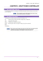
Craft ROBO Controller Components


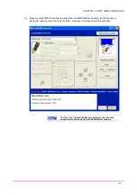
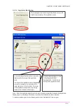
When the Craft ROBO Controller is launched, the following screen appears. 


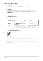
3.5.1  Hide/Show the operation guide 

When the Craft ROBO Controller is launched, the operation guide is displayed at the bottom of the window. 
The [Hide/Display the Operation Guide] button turns the operation guide function on/off. 

The operation guide provides step-by-step instructions for setting up and operating the Craft ROBO 
Controller. 


3.5.2  [Animated Instructions] Button 

The animated instruction describing operation of "Craft ROBO" and "Craft ROBO controller". 


3.5.3  [Help] Button 

Displays quick help 


3-11 

Summary of Contents for Craft ROBO CC100

Page 1: ...User s Manual MANUAL NO CC100m UM 152...

Page 2: ...installation If this equipment does cause harmful interference to radio or television reception which can be determined by turning the equipment off and on the user is encouraged to try to correct in...

Page 3: ...Size media 2 5 Using a Carrier Sheet for Letter Size media 2 6 Cutting area of the carrier sheet 2 7 2 4 Setting the Blade Length 2 8 Blade holder description 2 8 Blade adjustment caps and media sele...

Page 4: ...cluded with your product If any item is missing please contact your place of purchase AC adapter AC adapter Power cable 1 USB cable 1 Quick Start Instructions 1 Craft ROBO Software CD ROM 1 Media Tria...

Page 5: ...tting using a blade Clamp bracket Holds the blade holder penholder and drives it up or down Standby switch Turns on and off the cutter LED lamp The light is on when unit is ready to operate and flashe...

Page 6: ...adapter 2 Plug the AC adapter cable into the AC adapter jack of the cutter 3 Plug the other end of the power cable into the AC outlet 2 2 Connecting to a Computer Connect the cutter to a computer via...

Page 7: ...there is a loading direction printed on the sheet load the sheet to the Craft ROBO accordingly Standby switch LED lamp 3 While making sure the media is straight align the left edge of the sheet with t...

Page 8: ...s the media to feed properly but reduces the potential cutting area by 5 mm in the feed direction Align the edge of the media with the guideline indented at the rear of the unit Media Size Vinyl and m...

Page 9: ...a varies with the mode you select In standard mode the cutting area is 190 mm in width In expanded mode the cutting area is 200 mm in width If registration marks are used the cutting area is 190 mm in...

Page 10: ...r other problems Actual number may vary depending on a type of cut media Pulling out the carrier sheet without turning the feed knob may shorten its life causing misaligned cutting Always be sure to t...

Page 11: ...r sheet so that the adhesive surface is visible Peel off the liner inside and on both sides of the backing sheet Liner 2 Press the media onto the adhesive surface of the carrier sheet making sure that...

Page 12: ...of the carrier sheet is shown in the diagram below When using media smaller than Letter size always place the media within the cutting area In addition make sure the media is set parallel to the edge...

Page 13: ...media otherwise the cutting mat may be damaged Caution When handling the cutter blade exercise care to prevent injuring your hand Blade holder description The length of the blade protruding from the...

Page 14: ...Media Blue Thin film Yellow Thick film thin media Red Thick media Changing the blade adjustment caps The blade adjustment cap is a screw on type Blade holder Blade adjustment cap 1 Turn it in the coun...

Page 15: ...ock lever to the left OPEN direction and remove the blade holder Firmly insert the blade holder in place until this face contacts the holder Lock lever 2 When using the carrier sheet always use the st...

Page 16: ...r accepts cylinder pens up to 8 5 mm in diameter or hexagon shaped pens up to 7 5 mm side to side and whose tips extend between 3 and 3 5 mm past the ballpoint penholder s opening Cylindrical ball poi...

Page 17: ...kwise 2 Insert the ballpoint pen into the holder 3 Confirm that the tip of the ballpoint pen protrudes from the holder 3 mm 4 Tighten the thumbscrew by turning it clockwise 5 Turn the lock lever to th...

Page 18: ...e following lists the minimum system requirements for the software to run OS Windows 98 Second Edition Windows Me Windows 2000 or Windows XP CPU Pentium III 600 MHz or better Memory 128 MB minimum 256...

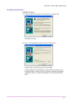
Page 19: ...If this window does not appear open My Computer and double click on CD Drive If the Start window still does not appear execute MultiSetup exe on the CD ROM When the Start window opens click on Install...

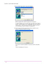
Page 20: ...ed 2 Next a Choose Destination Location screen will be displayed Select the folder in which the Controller is to be installed Unless the folder shown by default does not have sufficient free space it...

Page 21: ...e program icon to an existing folder select one from the list of Existing Folders A new folder named Craft ROBO is prepared by default if this is unnecessary to change click Next File copying starts 4...

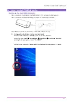
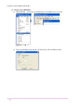
Page 22: ...by a USB cable Standby switch LED lamp The Craft ROBO Controller can be started up in either of the following two ways 1 Starting up from the Windows Start menu or the shortcut The Craft ROBO Control...

Page 23: ...O CONTROLLER 2 Starting up from ROBO Master a Click Craft ROBO in the File menu of ROBO Master or Craft ROBO icon on the toolbar b Output to Craft ROBO window will open Click OK to start up the Craft...

Page 24: ...is started from the ROBO Master software the Cut button is displayed enabling output from the controller otherwise it is replaced with Close button The Cut and Cancel buttons are displayed only when...

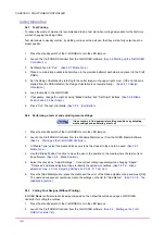
Page 25: ...essary to find appropriate cutting conditions by adjusting media settings and performing a test cut 1 Press the standby switch of the Craft ROBO to turn the LED lamp on 2 Launch the Craft ROBO Control...

Page 26: ...wn list See 3 5 7 Media Type 4 Replace the blade adjustment cap as prompted by graphical indicator See 3 5 7 A Blade Adjustment Cap 5 If cutting is not performed properly adjust the cutting conditions...

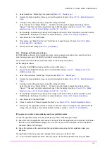
Page 27: ...stration in the Craft ROBO Controller See 3 5 11 C Registration Mark Reading 11 Press the Registration mark reading button It starts reading of the registration marks See 3 5 11 C Registration mark re...

Page 28: ...the operation guide is displayed at the bottom of the window The Hide Display the Operation Guide button turns the operation guide function on off The operation guide provides step by step instruction...

Page 29: ...media to be cut The setup items are listed below Thick Media Select this item when paper thicker than 0 13 mm is used Thin Media Select this item when paper thinner than 0 13 mm is used Pen Select th...

Page 30: ...utting speed and selecting Slow reduces the speed The slower the cutting speed the higher the cutting quality The speed can be adjusted in 10 steps Thickness Specifies the thickness of the media to be...

Page 31: ...er or carrier sheet If cutting is not properly done such as when the backing material is cut or the media is not cut perfectly adjust the degree to which the cutter blade protrudes Alternatively chang...

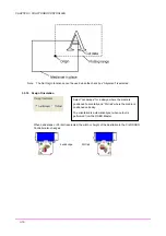
Page 32: ...ition using the Blade Position buttons click the Set Origin button and set current position to be specified as the origin Do not use this function while using registration marks Registration marks all...

Page 33: ...t Landscape for a design where the media is positioned horizontally and Portrait where the media is positioned vertically The orientation is automatically set when output is performed from the ROBO Ma...

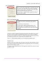
Page 34: ...read normally cutting is performed The function for reading the registration marks automatically searches for the registration marks within a fixed range from the current position of the blade pen tow...

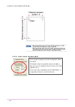
Page 35: ...tput the printed media may be distorted by heat resulting in a misaligned cutting 3 5 11 B Distance between Registration Marks These controls are displayed when Search Registration Marks is turned off...

Page 36: ...ade to within the range of the registration mark The range of the registration mark is displayed as a green rectangle in the illustration at the upper right corner of the Controller The range of the r...

Page 37: ...lly not necessary to perform this correction Follow the procedure described below to perform Registration Mark Sensor Position Correction To perform a Registration Mark Reading Test select Letter size...

Page 38: ...oss Intersection point of the printed or hand drawn cross Intersection point of the cross drawn by the Craft ROBO If the position of the intersection point recognized by the Craft ROBO is not aligned...

Page 39: ...the fed distance is greater than the expected distance or a positive value if the fed distance is less than the expected distance The correction value may be calculated from the equation below 1 actu...

Page 40: ...ctions in the message To install the software again first uninstall the Craft ROBO Controller currently installed If the problem is not solved download the latest version of the Craft ROBO Controller...

Page 41: ...eral purpose ballpoint pen used only with the ballpoint penholder Media types that can be cut Film Media 0 1 mm or less in thickness liner included thickness of 0 3 mm or less Inkjet or laser paper up...

Page 42: ...Mark Reading 3 19 Search Registration Mark 3 17 Set Origin 3 15 Craft ROBO Parts and Functions 1 2 Cutter Operation 3 8 Cutting Your Designs 3 8 If the system is unable to automatically read the regis...

Page 43: ...rmation contained herein is subject to change without notice CC100 User s Manual Issued November 9 2004 CC100m UM 152 1st edition 000 Issued by Graphtec Corporation 503 10 Shinano cho Totsuka ku Yokoh...

Reviews: