background image

31

309977

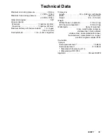
Technical Data

Maximum air working pressure

250 psi

. . . . . . . . . . . . . . 

(1.7 MPa, 17 bar)

Maximum fluid working pressure

580 psi

. . . . . . . . . . . . . 

(4.0 MPa, 40 bar)

Generator required

7 kW

. . . . . . . . . . . . . . . . . . . . . . . . . . 

Hopper capacity

Maximum

12 gallons (45 liters)

. . . . . . . . . . . . . . . . . . . 

Operating

10 gallons (38 liters)

. . . . . . . . . . . . . . . . . . . 

Maximum delivery with texture material

1 to 1.5 gpm

. . 

(3.8 to 5.7 lpm)

Fluid outlet size

1.0 in. (f) cam and groove

. . . . . . . . . . . 

Dimensions

Length

23 in. (584 mm) with handle

. . . . . . . . . . . . . . . . 

Width

24 in. (610 mm)

. . . . . . . . . . . . . . . . . . . . . . . . . . . 

Height

40 in. (1016 mm)

. . . . . . . . . . . . . . . . . . . . . . . . . 

Weight

Without hoses or applicator

113 lb (51 kg)

. . . . . . . . . . 

With hoses and applicator

125 lb (57 kg)

. . . . . . . . . . . 

Wetted parts

Buna–N, aluminum,

. . . . . . . . . . . . . . . . . . . 

brass, polyethylene, neoprene,

stainless steel, chrome-plated 

stainless steel, nickel-plated carbon steel,

fluoroelastomer, nickel-plated iron, inconel,

wool felt, tungsten carbide, PTFE

Sound data

Sprayer

Sound pressure level 

*

79 dB(A)

. . . . . . . . . . . . . . . . . . 

Sound power level 

{

87.5 dB(A)

. . . . . . . . . . . . . . . . . . . 

*

Measured while spraying at 1 m.

{

Measured per ISO-3744.

Applicator

Manual 309978

. . . . . . . . . . . . . . . . . . . . . . . . . 

Summary of Contents for T-Max 405 248195

Page 1: ...2004 Graco Inc is registered to I S EN ISO 9001 T Max 405t Texture Sprayer For Water Based Materials Only 40 Bar 4 MPa 580 psi Maximum Working Pressure Model 248195 Series A Model 248269 Series A Model 249075 Series A 309977 rev F Read warnings and instructions 309978 309973 ...

Page 2: ... Motor Replacement 13 Pressure Control Repair 15 Motor Control Board Diagnostics 15 Motor Control Board 16 Pressure Control Transducer 17 Pressure Adjust Potentiometer 17 Pump Repair 18 Bearing Housing Connecting Rod 21 Drive Housing 22 Parts Drawing 24 Parts List 25 Wiring Diagram 27 Technical Data 31 Graco Warranty 32 Graco Phone Number 32 ...

Page 3: ...MENT HAZARD Fluid from the applicator leaks or ruptured components can splash in the eyes or on skin and cause serious injury D Follow Pressure Relief Procedure in this manual when you stop spraying and before cleaning checking or servicing equipment D Tighten all fluid connections before operating the equipment D Check hoses tubes and couplings daily Replace worn or damaged parts immediately PERS...

Page 4: ...Hold hose firmly in one hand and slowly open one cam arm at a time Remove hose from pump outlet Grounding and Electrical Requirements WARNING Improper installation or alteration of the grounding plug will result in a risk of electric shock fire or explosion that could cause serious injury or death Voltage Requirements D Fig 1 220 240 Vac models require a 50 Hz 16A circuit with a grounding receptac...

Page 5: ...ach the 25 mm x 5m hose to the pump outlet Other hoses may then be added up to the maximum fluid hose lengths D Use shortest fluid hose length required for the spray application 25 mm x 5m minimum see Warning D Unnecessary hose length decreases sprayer performance D Maximum fluid hose lengths 15 m of 25 mm ID or 10 m of 25 mm ID combined with 3 m of 19 mm ID fluid hose WARNING The motor has a ther...

Page 6: ...aint hardened dried in sprayer replace pump packing See page 18 Pump Repair 2 Displacement pump connecting rod pin 75 Pin must be completely pushed into connecting rod 45 and retaining spring 76 must be firmly in groove of pump pin See Fig 9 2 Push pin into place and secure with spring re tainer 3 Motor 33 Remove drive housing assembly 37 See page 13 Try to rotate fan by hand 3 Replace motor 33 if...

Page 7: ...See page 11 9 Clean brush holders Remove carbon with small cleaning brush Align brush leads with slot in brush holder to assure free vertical brush movement 10 Motor armature commutator for burn spots gouges and extreme roughness See page 11 10 Remove motor and have motor shop resur face commutator if possible See page 13 11 Motor armature for shorts using armature tester growler or perform spin t...

Page 8: ...an 90 m 295 ft Longer cord lengths reduce sprayer performance 7 Replace with a correct grounded exten sion cord 8 Leads from motor to pressure control circuit board 38 for damaged or loose wires or con nectors Inspect wiring insulation and terminals for signs of overheating 8 Be sure male terminal blades are centered and firmly connected to female terminals Replace any loose terminal or damaged wi...

Page 9: ...ing around throat packing nut which may indicate worn or damaged packings See page 18 4 Replace packing page 18 Also check pis ton valve seat for hardened paint or nicks and replace if necessary Tighten packing nut 5 Pump rod damage 5 Repair pump page 18 6 Capacitor failure Visually inspect capacitor near terminals Ensure that orange safety re lief plug is intact 6 Replace capacitor Motor runs but...

Page 10: ... page 11 Inspect windings for burns 3 Replace motor See page 13 4 Motor control board 38 by performing motor control board diagnostics on page 15 If diag nostics indicate substitute with a good board CAUTION Do not perform this check until mo tor armature is determined to be good A bad motor armature can burn out a good board 4 Replace with a new pressure control board 38 See page 15 1 Basic Elect...

Page 11: ... no resistance check for broken brush springs brush leads motor leads loose brush terminal screws motor lead terminals worn brushes Repair as needed page 11 3 If still uneven or no resistance replace motor page 13 Fig 2 ti4816a 155 A Motor Brush Replacement Motor Brush Removal Replace brushes worn to less than 1 2 in Check both sides Order Brush Repair Kit 243642 for 220 240 Vac motors and 243215 ...

Page 12: ...5a Fig 4 9 Inspect commutator for excessive pitting burning or gouging A black color on commutator is normal Have commutator resurfaced by a motor repair shop if brushes wear too fast 10 Test brushes a Disconnect pump 31 Pump Repair Removal steps 8 and 9 page 18 b With sprayer OFF turn pump control knob fully counterclockwise to minimum pressure Plug in sprayer c Turn sprayer ON Slowly increase pr...

Page 13: ...or front end bell or drive housing 9 Return motor and drive housing assembly to vertical position 10 Remove four screws 85 and washers 84 Remove motor 33 from drive housing 37 Installation CAUTION When installing motor carefully align gears to avoid damaging mating parts 1 Fig 6 Place new motor 33 on drive housing 37 Rotate fan C When gears are felt to mesh install four washers 84 and screws 85 2 ...

Page 14: ...14 309977 Motor Replacement 90_ 12 18 2 Yellow 42 85 33 37 86 84 85 84 84 25 42 41 40 71 90 D C ti4811a B 41 49 83 38 12 Fig 6 ...

Page 15: ...s sure greater than 57 bar 5 7 MPa 830 psi Replace pressure transducer or motor control board See following Motor Control Board procedure Three times repeatedly Sprayer shuts down and LED continues to blink three times repeatedly Pressure transducer is faulty or missing Check transducer connection Open drain valve Substitute new transducer for transducer in sprayer If sprayer runs replace transduc...

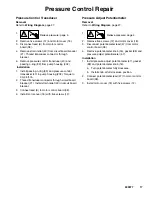
Page 16: ...d circuit board 38 Installation CAUTION Electrostatic discharges can damage components on motor control board Use a ground strap when handling or installing motor control board 1 Fig 7 Remove old thermal paste from control box Remove protective cover from thermal pad on new motor control board Fig 7 ti8397a 2 Fig 6 Install motor control board 38 with six screws 83 3 Connect to motor control board ...

Page 17: ...cer connector through circuit board bracket 21 Install strain relief 49 in circuit board bracket 3 Connect lead E to motor control board 38 4 Install motor cover 18 with five screws 12 Pressure Adjust Potentiometer Removal Refer to Wiring Diagram page 27 1 Relieve pressure page 4 2 Remove five screws 12 and motor cover 18 3 Disconnect potentiometer lead 47 from motor control board 38 4 Remove pote...

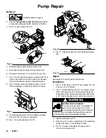
Page 18: ...0 Fig 10 Loosen retaining nut 27 Fig 10 49 B 38 27 11 Fig 11 Unscrew pump 31 from bearing housing 34 ti4622a 31 203 34 Fig 11 Repair See page 19 for pump repair instructions Installation 1 Fig 17 Push piston rod 203 out of pump 31 50 to 75 mm 2 to 3 inches 2 Fig 11 Screw retaining nut 27 onto pump until it stops Screw pump 31 into bearing housing 34 until pump stops Unscrew pump until pump outlet ...

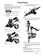
Page 19: ...ve clamp 209 and pump cylinder 201 ti5132a 201 209 Fig 13 5 Fig 14 Remove packing nut 216 Push piston rod 203 from outlet housing 202 ti5131a 216 202 203 Fig 14 6 Place end of piston rod in vise and remove piston valve 217 Remove piston seal 222 Fig 15 203 222 217 220 ti4804a 7 Inspect all part for nicks and scratches Replace worn or damaged parts as they may result in poor pump performance Repair...

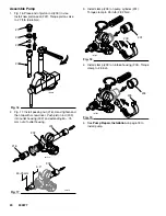
Page 20: ...and then tap with screw driver Push piston rod 203 into outlet housing 202 and extending 50 75 mm out of outlet housing Fig 17 ti5131a 216 202 203 ti5131a 203 2 3 50 75mm 3 Install clamp 209 on pump cylinder 201 Torque clamp to 25 in lb 2 82 N m ti5132a 201 209 Fig 18 4 Install clamp 209 on intake housing 204 Torque clamp to 25 in lb Fig 19 ti5132a 204 209 5 See Pump Repair Installation on page 18...

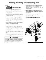
Page 21: ... roller bearing B lower bearing C inside connecting rod assembly 45 with bearing grease 2 Assemble connecting rod 45 and bearing housing 34 3 Clean mating surfaces of bearing housing 34 and drive housing 37 CAUTION Do not use bearing housing screws 7 to align or seat bearing housing with drive housing Align these parts with locating pins D to avoid premature bearing wear 4 Align connecting rod wit...

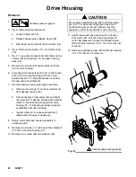
Page 22: ...ing with a plastic mallet to loosen bearing housing from drive housing 37 Pull bearing housing and pump assemblies from drive housing c Inspect crank G for excessive wear and replace drive housing if necessary 8 Return motor and drive housing assembly to vertical position 9 Remove two screws 12 and circuit board bracket 21 from from drive housing 37 10 Remove four screws 85 and washers 84 CAUTION ...

Page 23: ...and pump assembly a Align connecting rod with crank G and carefully align locating pins H in drive housing 37 with holes in bearing housing 34 b Push bearing housing and pump assemblies onto drive housing Push connecting rod assembly 45 and lightly tap lower front of bearing housing with a plastic mallet to seat bearing housing to drive housing 37 c Install bearing housing 34 with four screws 7 an...

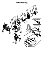
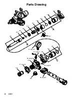
Page 24: ...28 35 1 3 20 31 pg 28 51 37 pg 26 25 page 26 36 72 67 65 81 13 22 47 160 61 58 55 2 32 26 53 94 12 49 38 27 43 42 41 39 21 19 5 71 50 82 12 12 16 40 56 48 95 47 90 9 61a 61b 61c 57 89 83 93 88 87 161 ti4101b 163 162 165 24 309977 Parts Drawing ...

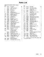
Page 25: ...pplicator 1 47PM 236352 POTENTIOMETER adj press 1 48PM 118506 COUPLER male 1 in npt 1 includes165 49PM 114678 BUSHING strain relief 2 50PM 119284 PIN straight slotted 1 51PM 248391 GAUGE pressure pump texture 1 53 15D151 RING retainer hopper 1 55 248519 HOSE fluid 25 mm x 5 m 1 includes 165 56 100333 SCREW cap hex hd 1 57 118751 TIE lanyard 1 58 248520 HOSE fluid 19 mm x 3 m cpld 1 includes 165 61...

Page 26: ...7 Parts Drawing ti4097b 31 75 27 76 34 7 6 25 45 37 10 11 33 71 79 85 84 84 86 90 82 153 152 150 Denmark Italy Switzerland 154 151 14 29 106 102 74 73 Model 248269 Model 248195 111 110 109 112 Model 249075 156 ...

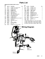
Page 27: ... 79 15E107 LEG support pump 1 82 111040 NUT lock 6 84PM 105510 WASHER lock spring hi collar 6 85PM 100644 SCREW cap sch 4 86PM 107218 SCREW cap sch 2 90PM 101888 SCREW cap sch 4 102PM 192840 LABEL warning 1 106PM 187436 LABEL torque 1 109PM 118715 FAN motor 1 110PM 15E287 BUSHING shaft fan 1 111PM 103253 SCREW set hex soc 1 112PM 113983 RING retaining ext 1 150 195551 RETAINER adapter cord 1 151 1...

Page 28: ...48 page 24 43 page 24 27 page 24 51 page 24 50 page 24 204 208 207 206 202 216 231 230 203 209 209 201 222 210 217 220 231 89 page 24 A B C ti4796a 211 229 28 309977 Parts Drawing ...

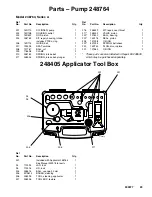
Page 29: ...529 KIT repair seal throat 1 217 248232 VALVE piston 1 220 101822 BALL bearing 1 222 15D116 SEAL piston 1 228 107098 O RING 1 229 501095 SPRING ball check 1 230 15D740 PLUG disc rupture 1 231 107563 O RING 2 These parts are also included in Repair Kit 248530 which may be purchased separately 248405 Applicator Tool Box 301 94 95 304 305 306 211 TI4817a 307 Ref No Part No Description Qty 301 Include...

Page 30: ...30 309977 Notes ...
Page 31: ...groove Dimensions Length 23 in 584 mm with handle Width 24 in 610 mm Height 40 in 1016 mm Weight Without hoses or applicator 113 lb 51 kg With hoses and applicator 125 lb 57 kg Wetted parts Buna N aluminum brass polyethylene neoprene stainless steel chrome plated stainless steel nickel plated carbon steel fluoroelastomer nickel plated iron inconel wool felt tungsten carbide PTFE Sound data Sprayer...

Page 32: ...remedy including but not limited to incidental or consequential damages for lost profits lost sales injury to person or property or any other incidental or consequential loss shall be available Any action for breach of warranty must be brought within two 2 years of the date of sale Graco makes no warranty and disclaims all implied warranties of merchantability and fitness for a particular purpose ...

Reviews: