background image

Instructions - Parts List

PrecisionSwirl


Module

An orbital dispenser used to apply sealant and adhesive materials for a variety of 
applications.

Part No. 241658, 234029, 289911 and 289912

3500 psi (24.1 MPa, 241 bar) Maximum Fluid Working Pressure

See page 2 for List of Models.

U.S. Patent No. 6,499,673
EU Patent No. 0852160

Important Safety Instructions

Read all warnings and instructions in this manual. 
Save these instructions.

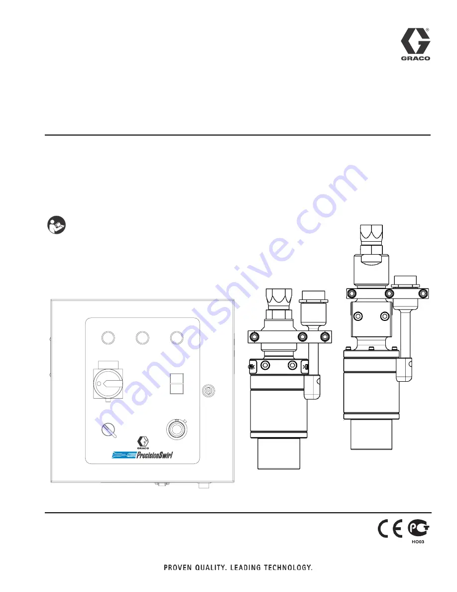
PrecisionSwirl

Orbital Dispenser

243402 and 243403

POWER 

MOTOR FAULT 

RUN 

MAIN 

RUN / ENABLE 

CONTROL 

S

ELECT 

AUTOMATIC 

MANUAL 

MANUAL 

S

PEED CONTROL 

8037B

PrecisionSwirl Control Assembly

918616

289261 and 289262

PrecisionSwirl

Orbital Dispenser

310554V

ENG

Summary of Contents for PrecisionSwirl 234029

Page 1: ...sure See page 2 for List of Models U S Patent No 6 499 673 EU Patent No 0852160 Important Safety Instructions Read all warnings and instructions in this manual Save these instructions PrecisionSwirl O...

Page 2: ...Control Assembly Kit includes 233123 289261 617829 617870 and 918616 Part No 289912 Series A PrecisionSwirl Orbital Dispenser and Control Assembly Kit includes 233123 289262 617829 617870 and 918616 P...

Page 3: ...rifying Ground Continuity 20 Adjusting the Orbital Dispenser 20 Inspecting the Orbital Dispenser 20 Grounding the System 20 PrecisionSwirl Module Operation 21 Reading the PrecisionSwirl Control Assemb...

Page 4: ...d parts immediately Do not exceed the maximum fluid working pressure of 3500 psi 241 bar 24 1 MPa to the dispenser or manifold Never exceed the recommended working pressure or the maximum air inlet pr...

Page 5: ...e Relief Procedure from manual 309403 then remove the nozzle to clean it Never wipe off build up around the nozzle or inlet cap until pressure is fully relieved FIRE AND EXPLOSION HAZARD Improper grou...

Page 6: ...o avoid the buildup of vapors from the fluid being dispensed Know the specific hazards of the fluid you are using Store hazardous fluid in an approved container Dispose of hazardous fluid according to...

Page 7: ...Warnings 310554V 7...

Page 8: ...on the purchaser can have the unit repaired by an authorized Graco distributor For addi tional information read the following subsections On site Service PrecisionSwirl components are customarily serv...

Page 9: ...ensed The orbital dispenser applies a continuous swirled bead of material directly on components in targeted areas such as the hem flanges on car doors the interior seams of the chassis and on the fix...

Page 10: ...ol assembly PrecisionSwirl 2 Orbital dispenser PrecisionSwirl 4 Automatic control cable PrecisionSwirl Also called robot interface cable in this manual 5 6 9 or 15 ft 1 8 2 7 or 4 6 m flexible motor c...

Page 11: ...sembly approximately 24 67 in 0 6 1 7 m above the floor Make sure all cables reach components without strain Make sure there is sufficient space for repair main tenance and operation of the robot and...

Page 12: ...50 368 3 mm 16 00 152 4 mm NOTE Hidden lines depict the hole pattern for mounting the control assembly NOTE Conrol assembly must be readily accessible and located 24 67 in 0 6 1 7 m above the floor 7...

Page 13: ...ng must be 8 AWG 8 36 mm2 minimum A qualified electrician must complete all grounding and wiring connections Refer to your local code for the requirements for a true earth ground in your area Also rea...

Page 14: ...aker 6 Move the POWER switch to the ON position apply ing power to the control assembly ELECTRIC SHOCK HAZARD Do not connect the PrecisionSwirl control assembly to a power source unless you are a trai...

Page 15: ...th ground The resistance must be less than 0 25 ohms If the resistance is greater than 0 25 ohms a different ground site may be required Do not operate the Preci sionSwirl module until the problem is...

Page 16: ...head screws 38 and flat washers 39 Connecting Air Lines to Dispense Valve Securely connect air lines to dispense valve air ports F Make sure to connect the appropriate air lines to the appropriate po...

Page 17: ...correctly 4 Route the motor control cable and conform to the following cable routing requirements Avoid a bend radius of less than 5 in 12 7 cm Avoid pinch points Avoid cable pulling or stretching Kee...

Page 18: ...Installing Cable Assemblies 18 310554V Connecting the Motor Control Cable continued FIG 9 0 7 2 4 2 5 4 25 25 42 3 4 54 4 5 5 30 42 ti0657B Motor Control Cable 15 ft Motor Control Cable 55 ft...

Page 19: ...d FIG 11 5 Check the connections to ensure the cable is con nected correctly CAUTION Always make connections to the control assembly with power turned off Any wiring from an external source such as a...

Page 20: ...em may include other equipment or objects which must be grounded Check your local electrical code for detailed grounding instructions for your area and type of equipment Your system must be connected...

Page 21: ...s a robot via an interface cable In the MANUAL position the orbital dispenser is controlled directly from the control assembly front panel RUN ENABLE Button Pushing the RUN ENABLE black button starts...

Page 22: ...Swirl orbital dispenser is in an idle state until you press the RUN ENABLE button on the control assembly The only time the PrecisionSwirl orbital dis penser can swirl material is when the RUN ENABLE...

Page 23: ...e RUN ENABLE black button Make sure the green RUN indicator shown in FIG 12 is lit at the control assembly The PrecisionSwirl orbital dispenser motor starts imme diately Stop Manual Swirling To stop m...

Page 24: ...find the manual control setting required to achieve the desired motor speed Automatic Mode Use the motor speed chart FIG 13 to find the voltage setting required to achieve the desired motor speed Whe...

Page 25: ...roblem Cause Solution No material being dispensed Clogged nozzle Change nozzle No material or pressure Check fluid delivery system Broken or clogged dispense tube Rebuild the orbital dispenser Fault i...

Page 26: ...control assembly 5 Verify that the replaced fixture operates correctly 6 Return the orbital dispenser and control assembly to normal operating condition Light Bulb Removal Remove the light bulb as fo...

Page 27: ...itch assembly to the yellow mount ing plate with two flat head screws 2 Assemble the red rotor which is keyed onto the yel low mounting plate with one flat head screw See Fig 15 3 Turn the rotor to po...

Page 28: ...to its stop 3 Pre set the vernier dial to 0 00 and place it over the potentiometer shaft with its key tab inserted into the blind hole in the cover front surface Tighten the dial setscrew not shown a...

Page 29: ...owing panel assembly components Swirl Control Board page 30 RFI Filter page 31 Relay page 32 Fuse page 33 FIG 17 6 6 3 3 3 2 2 9 54 0 6 0 6 6 0 4 4 2 0 4 4 2 0 4 4 2 3 4 54 34 0 0 25 4 25 0 34 0 0 4 2...

Page 30: ...ay board as follows 1 Snap the swirl control board onto the din rail 2 Plug the connectors into the swirl control board Refer to FIG 17 for lead wire identification 3 Close and lock the hinged cover o...

Page 31: ...ce the RFI filter as follows 1 Install the RFI filter using the two screws and lock washers to secure the component on the panel assembly See FIG 17 2 Connect the wires to the correct terminal block o...

Page 32: ...Apply system power at the main circuit breaker 4 Move the MAIN power switch to the ON position applying power to the control assembly 5 Verify that the relay operates correctly 6 Return the control a...

Page 33: ...lose and lock the fuse holder into place 3 Close and lock the hinged cover on the control assembly 4 Apply system power at the main circuit breaker 5 Move the MAIN power switch to the ON position appl...

Page 34: ...14 617778 LENS light white 7 8 1 15 617779 LENS light green 7 8 1 16 617780 LAMP incandescent 24V 2 17 617781 SWITCH BASE 1 NO 1 NC 2 18 617782 ACTUATOR switch 2 PB rect 1 19 617783 ACTUATOR switch 2...

Page 35: ...s 310554V 35 Part No 918616 PrecisionSwirl Control Assembly FIG 20 POWER MOTOR FAULT RUN MAIN RUN ENABLE CONTROL SELECT AUTOMATIC MANUAL MANUAL SPEED CONTROL 0 7 2 3500 9 54 4 42 4 2 2 1 20 21 31 8 4...

Page 36: ...Control Assembly Parts 36 310554V Part No 918616 PrecisionSwirl Control Assembly FIG 21 13 53 16 13 15 16 17 18 13 14 16 9 36 45 48 52 17 19 35...

Page 37: ...Control Assembly Parts 310554V 37 Part No 918616 PrecisionSwirl Control Assembly FIG 22 2 2 2 0 6 0 42 43 16 3...

Page 38: ...10 514556 HOLDER fuse 2 11 115234 COVER terminal 1 12 112446 BLOCK clamp end 7 13 112442 BLOCK terminal 23 14 103833 SCREW machine bdgn 12 15 115212 FILTER RFI 1 16 194894 DUCT wire 1 21 194976 LABEL...

Page 39: ...Control Assembly Parts 310554V 39...

Page 40: ...alone Table 5 Motor Control Cables Part Number Length Description 617870 55 ft 16 8 m Motor cable assembly FIG 24 P N 617870 SOCKET PIN A B C D E H J K L M A B C D E H J K L M WHITE BROWN GREEN YELLOW...

Page 41: ...cables must be used in conjunction with the 55 ft motor cable Table 6 Motor Control Cables Part Number Length Description 233125 6 ft 1 8 m Motor cable assembly 233124 9 ft 2 7 m Motor cable assembly...

Page 42: ...IG 26 P N 617829 1 2 3 4 5 6 7 8 9 SHIELD RED GREEN BLACK GREEN BLACK CONNECTION DIAGRAM REFERENCE FUNCTION 0 10 VDC ANALOG SPEED CONTROL ORANGE BLACK RED BLUE WHITE BLACK WHITE 0 10 VDC ACTUAL SPEED...

Page 43: ...Wiring Diagrams 310554V 43 Wiring Diagrams Motor Controller Wiring Lines 200 238 6 0 7 2 3500 9 2 2 25 2 2 2 2 2 34 0 54 2 2 2 2 7 5 2 2 2 6 37 2 2 4 6 6 6 6 4 2...

Page 44: ...Wiring Diagrams 44 310554V Motor Controller Wiring Lines 250 288 2 37 2 42 25 5 84 2 54 4 42 6 54054 6 25 6 2 2 9 54 2 2 9 054 0 0 0 0 0 0 0 0 6 3 3 3 6 0 4...

Page 45: ...or 6600 24 000 RPM Speed signal output 0 10 VDC for 0 24 000 RPM Auto control relay contact rating 3 Amps at 30 VDC Weight 23 5 lbs 10 7 kg Orbital Dispenser Input power Proprietary PWM voltage to the...

Page 46: ...anship repairs will be made at a reasonable charge which charges may include the costs of parts labor and transportation THIS WARRANTY IS EXCLUSIVE AND IS IN LIEU OF ANY OTHER WARRANTIES EXPRESS OR IM...

Reviews: