background image

Setup

Pressure

Pressure

Pressure Relief

Relief

Relief Procedure

Procedure

Procedure

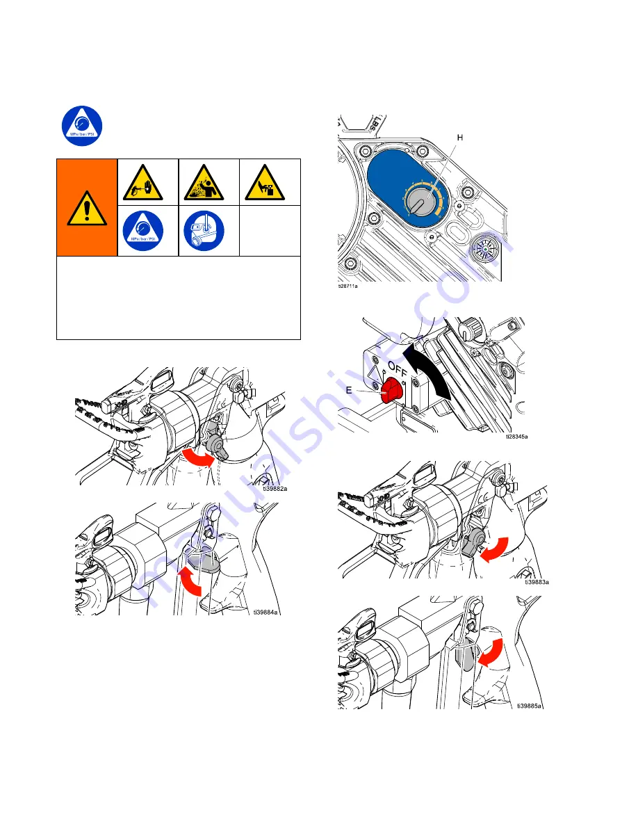
Follow the Pressure Relief Procedure
whenever you see this symbol.

This equipment stays pressurized until pressure
is manually relieved. To help prevent serious
injury from pressurized fluid, such as skin injection,
splashing fluid and moving parts, follow the
Pressure Relief Procedure when you stop spraying
and before cleaning, checking, or servicing the
equipment.

1.

Engage gun trigger lock.

XTR

XTR

XTR Gun

Gun

Gun

XHF

XHF

XHF Gun

Gun

Gun

2.

Pull pressure adjustment knob (H) out and turn
counterclockwise until it stops. Push the knob
in to lock.

3.

Turn power switch (E) OFF.

4.

Disengage gun trigger lock.

XTR

XTR

XTR Gun

Gun

Gun

XHF

XHF

XHF Gun

Gun

Gun

12

3A8126B

Summary of Contents for King E50

Page 1: ...ive protective protective coatings coatings coatings For For For professional professional professional use use use only only only Important Important Important Safety Safety Safety Instructions Instructions Instructions Read all warnings and instructions in this manual and related manuals before using the equipment Save Save Save all all all instructions instructions instructions See page 3 for m...

Page 2: ... Troubleshooting 23 Standby Mode 23 Error Codes Table 23 Repair 25 Xtreme Lower Removal 25 Disconnect and Reconnect Lower 25 Outlet Check Valves 26 Parts 27 Parts Drawing 27 Cart Parts 30 Outlet Check Valves Parts 31 Dimensions 33 Notes 36 Technical Specifications 37 California Proposition 65 38 Recycling and Disposal 39 Graco Standard Warranty 40 Related Related Related Manuals Manuals Manuals Ma...

Page 3: ... Heavy Duty Cart X 273254 King E50 Light Weight Cart X 273255 King E50 Light Weight Cart X 273256 King E50 Wall Mount X 273257 King E50 Wall Mount X 145 cc Integrated For maximum working pressure see Technical Technical Technical Specifications Specifications Specifications page page page 37 37 37 Lower Fluid temperature due to XTR gun Heavy Heavy Heavy Fluids Fluids Fluids Packages Packages Packa...

Page 4: ...nless they are antistatic or conductive Stop Stop Stop operation operation operation immediately immediately immediately if static sparking occurs or you feel a shock Do not use equipment until you identify and correct the problem Keep a working fire extinguisher in the work area Static charge may build up on plastic parts during cleaning and could discharge and ignite flammable vapors To help pre...

Page 5: ...rigger guard installed Engage trigger lock when not spraying Do not point gun at anyone or at any part of the body Do not put your hand over the spray tip Do not stop or deflect leaks with your hand body glove or rag Follow the Pressure Pressure Pressure Relief Relief Relief Procedure Procedure Procedure when you stop spraying and before cleaning checking or servicing equipment Tighten all fluid c...

Page 6: ...nd solvent manufacturer s warnings For complete information about your material request Safety Data Sheets SDSs from distributor or retailer Do not leave the work area while equipment is energized or under pressure Turn off all equipment and follow the Pressure Pressure Pressure Relief Relief Relief Procedure Procedure Procedure when equipment is not in use Check equipment daily Repair or replace ...

Page 7: ...urge Valve D Packing Nut E Power Switch Lock out tag out equipped F Fluid Outlet G Junction Box Cover H Pressure Adjustment Knob J Outlet Check Valve L Status Indicator Light LED P Oil Fill Cap vented S Junction Box T Filter Cap models equipped with integrated filter only U Material Suction Hose NOTE NOTE NOTE See the King Driver Operation Repair manual for warning label information 3A8126B 7 ...

Page 8: ... local code Object Object Object being being being sprayed sprayed sprayed Ground the object being sprayed Follow local code Solvent Solvent Solvent pails pails pails used used used when when when flushing flushing flushing Follow local code Use only conductive metal pails placed on a grounded surface Do not place the pail on a non conductive surface such as paper or cardboard which interrupts gro...

Page 9: ...rary cap must be replaced with the supplied vented oil cap P before use PX P ti31010a Flush Flush Flush Before Before Before Using Using Using Equipment Equipment Equipment The pump fluid section was tested with lightweight oil which is left in the fluid passages to protect parts To avoid contaminating your fluid with oil flush the equipment with a compatible solvent before using the equipment See...

Page 10: ... Seal Liquid TSLTM W WL L E E 7 7 6 6 4 Attach electrically conductive fluid hose to pump lower outlet via outlet check valve and tighten NOTICE NOTICE NOTICE Attaching the hose directly to the lower pump can result in damage to the sprayer during cavitation or when the sprayer runs out of material Use an outlet check valve between the lower pump and hose to avoid damage NOTICE NOTICE NOTICE The m...

Page 11: ...sted inner diameter is 1 in 2 5 cm 7 Check oil level NOTICE NOTICE NOTICE Only use oil with Graco part number 16W645 Any other oil may not lubricate properly and can cause damage to the drive train 8 Always flush and prime sprayer before each use see Prime Flush Prime Flush Prime Flush page page page 14 14 14 3A8126B 11 ...

Page 12: ...fluid such as skin injection splashing fluid and moving parts follow the Pressure Relief Procedure when you stop spraying and before cleaning checking or servicing the equipment 1 Engage gun trigger lock XTR XTR XTR Gun Gun Gun XHF XHF XHF Gun Gun Gun 2 Pull pressure adjustment knob H out and turn counterclockwise until it stops Push the knob in to lock 3 Turn power switch E OFF 4 Disengage gun tr...

Page 13: ... you suspect the spray tip or hose is completely clogged or that pressure has not been fully relieved a VERY SLOWLY loosen the tip guard retaining nut or hose end coupling to relieve pressure gradually b Loosen the nut or hose end coupling completely c With tip removed trigger the gun into the bucket Gun Gun Gun Trigger Trigger Trigger Lock Lock Lock Always engage the gun trigger lock when you sto...

Page 14: ...ssure 1 Perform Pressure Pressure Pressure Relief Relief Relief Procedure Procedure Procedure page page page 12 12 12 2 Remove tip and tip guard from gun 3 Place material suction hose U into compatible fluid if priming or solvent if flushing 4 Close drain valve C 5 Turn power switch E ON 6 Prime or flush hose and gun a Disengage gun trigger lock XTR XTR XTR Gun Gun Gun XHF XHF XHF Gun Gun Gun 14 3...

Page 15: ... harden in valve and result in clogging 8 Perform Pressure Pressure Pressure Relief Relief Relief Procedure Procedure Procedure page page page 12 12 12 9 Turn power switch E ON 10 To start pump pull out pressure adjustment knob H and turn clockwise slowly to increase pressure until a steady stream flows from drain valve Push knob in to lock NOTE NOTE NOTE To determine the proper amount of solvent ...

Page 16: ...Setup 15 Check pump and gun filters for debris 16 3A8126B ...

Page 17: ...Pressure Relief Relief Relief Procedure Procedure Procedure page page page 12 12 12 3 Install tip and tip guard onto gun Close the drain valve 4 Turn power switch E ON 5 Pull out and turn pressure adjustment knob H until desired pressure is reached Turn clockwise to increase pressure counterclockwise to decrease pressure Push knob in to lock 6 Disengage gun trigger lock XTR XTR XTR Gun Gun Gun XHF...

Page 18: ...r Bar MPA MPA MPA 1 500 35 0 3 5 400 27 2 7 2 1000 70 0 7 0 800 54 5 4 3 1500 105 10 5 1200 81 8 1 4 2000 140 14 0 1600 108 10 8 5 2500 170 17 0 2000 135 13 5 6 3000 205 20 5 2400 162 16 2 7 3500 240 24 0 2800 189 18 9 8 4000 275 27 5 3200 216 21 6 9 4500 310 31 0 3600 243 24 3 10 5000 344 34 4 4000 270 27 0 The sprayer can stall at pressures higher than the dynamic pressure All components downstr...

Page 19: ...sh a preventive maintenance schedule by recording when and what kind of maintenance is needed and then determine a regular schedule for checking your system Change Change Change the the the Oil Oil Oil NOTE NOTE NOTE Change the oil after a break in period of 200 000 300 000 cycles After the break in period change the oil once a year 1 Place a minimum 2 quart 1 9 liter container under the oil drain...

Page 20: ...NOTE NOTE The driver gear box is pre filled with oil The temporary unvented cap PX prevents oil leaks during shipment This temporary cap must be replaced with the supplied vented oil cap P before use NOTICE NOTICE NOTICE Only use oil with Graco part number 16W645 Any other oil may reduce the life of the gears Corrosion Corrosion Corrosion Protection Protection Protection Always flush the pump befo...

Page 21: ...er manual In the future stop the pump at the bottom of the stroke Keep the wet cup filled with compatible solvent Pump will not operate Driver parts are worn or damaged Repair or replace the driver Remove the lower from the driver If the driver will not cycle and does not blink an error code then troubleshoot the driver or replace Fluid is leaking from the rupture disk Replace the rupture disk do ...

Page 22: ...ubmerged Submerge the agitator mixer Air bubbles in fluid Agitator mixer RPM is too high Lower the agitator mixer RPM Incorrect fluid pressure at gun See the gun manual Read the fluid manufacturer s recommendations Fluid is too thin or too thick Adjust the fluid viscosity Read the fluid manufacturer s recommendations Poor finish or irregular spray pattern Dirty worn or damaged spray gun Service th...

Page 23: ...FF and ON Error Error Error Codes Codes Codes Table Table Table Blink Blink Blink Code Code Code Error Error Error Type Type Type Troubleshooting Troubleshooting Troubleshooting Steps Steps Steps 1 Alarm Pump Pump Pump diving diving diving The pump is diving rapidly A pressure imbalance between the up and down stroke of the pump is causing the pump to dive with excessive speed Pump diving may occu...

Page 24: ...larm Encoder Encoder Encoder Error Error Error Cycle power and check the status indicator L to see if the error is still active Verify that the internal connections are intact Contact your Graco distributor or Tech Service for more information 10 Alarm Software Software Software Versions Versions Versions Do Do Do Not Not Not Match Match Match Obtain software update token See Accessories Accessori...

Page 25: ...Procedure Procedure Procedure page page page 12 12 12 3 Disconnect the unit from the power source 4 Disconnect the fluid hose then disconnect the suction hose Hold the fluid inlet fitting with a wrench to keep it from loosening while you disconnect the suction hose Do not lift the pump by the lift ring when the weight exceeds 360 kg 800 lb The lift ring could fail and result in injury Use caution ...

Page 26: ... check valve then remove the outlet check valve from the pump lower NOTE NOTE NOTE The pressure drain valve may remain attached to the outlet check valve housing during repair if needed 7 Remove the outlet check valve nut from the valve housing 8 Remove and clean all internal outlet check valve components Inspect all components for wear or damage and replace components as needed 9 Reassemble parts...

Page 27: ...ion on Warning Labels see Driver Operation Repair manual 1 Torque to 145 155 ft lb 196 210 N m Quick Start Guide 3A8168 not shown is available upon request 2 Apply thread locker Wall mount sprayers only 3 Torque to 56 60 ft lb 68 81 N m 4 Apply lithium grease lubricant 3A8126B 27 ...

Page 28: ... 1 13 197340 COVER coupler 1 113361 CAP tube round Models 273246 273247 273252 273253 273262 273264 2 14 16W767 CAP tube round Models 273248 273249 273254 273255 2 17 126939 FITTING elbow Models 273262 273264 1 113362 WHEEL semi pneumatic heavy duty Models 273246 273247 273252 273253 273262 273264 2 20 116406 WHEEL semi pneumatic light weight Models 273248 273249 273254 273255 2 21 154628 WASHER M...

Page 29: ... m 5 gal to 1 1 4 NPT Models 273246 273247 273248 273249 273252 273253 273254 273255 1 74 20A584 HOSE suction 10 ft 3 m 55 gal to 1 1 4 NPT Models 273250 273251 273256 273257 1 76 19B967 GUARD Rod Coupler 2 81 17D554 BRACKET hopper upper Models 273262 273264 1 82 17C474 BRACKET hopper Models 273262 273264 1 83 112395 SCREW cap flng hd Models 273262 273264 4 84 16U537 COVER complete Models 273262 2...

Page 30: ...3 154628 WASHER 2 4 113436 RING retaining 2 5 113361 CAP tube round 2 C1 CART heavy duty 1 C3 113362 WHEEL semi pneumatic 2 Ref Ref Ref Part Part Part Description Description Description Qty Qty Qty 4 113436 RING retaining 2 C2 CART light weight 1 C4 116406 WHEEL semi pneumatic 2 C5 16W767 PLUG tubing 2 30 3A8126B ...

Page 31: ...check 1 6 181535 RETAINER spring 1 7 108361 SPRING compressor 1 23 245143 VALVE pressure bleed 1 If the outlet check valve is disassembled the o ring 2 must be replaced The o ring is designed to be crushed and not reused Parts Parts Parts Specifications Specifications Specifications Ref Ref Ref Instruction Instruction Instruction 1 Torque to 101 108 N m 75 80 ft lb 2 Apply lubricant Accessories Ac...

Page 32: ...X110 UL UL UL Listed Listed Listed File File File No No No E85994 E85994 E85994 IEEE IEEE IEEE 1580 1580 1580 Type Type Type P P P CSA CSA CSA C22 2 C22 2 C22 2 No No No 245 245 245 Type Type Type X110 X110 X110 IEC IEC IEC 60092 60092 60092 350 350 350 API API API RP14F RP14F RP14F Per manufacturer General Cable suitable for use in Class I Division 1 and Zone 1 Hazardous Locations when installed ...

Page 33: ...Dimensions Dimensions Dimensions Dimensions Wall Wall Wall Mount Mount Mount Systems Systems Systems 3A8126B 33 ...

Page 34: ...Dimensions Cart Cart Cart Systems Systems Systems 34 3A8126B ...

Page 35: ...Dimensions Hopper Hopper Hopper Systems Systems Systems 3A8126B 35 ...

Page 36: ...Notes Notes Notes Notes 36 3A8126B ...

Page 37: ...il capacity 1 0 1 2 quarts 0 9 1 1 liters Oil specification Graco part number 16W645 silicone free ISO 220 synthetic EP gear oil Weight Cart 330 lbs 150 kg Wall Mount 220 lbs 100 kg Inlet Outlet Sizes Fluid inlet size 1 1 4 in npt m also includes 1 in nps swivel to 1 in npt m adapter elbow Fluid outlet size 1 2 npt m also includes 1 2 npt f to 3 8 npt m adapter Hose Requirements Minimum pressure T...

Page 38: ...ht Cart 330 lbs 150 kg Wall Mount 220 lbs 100 kg Inlet Outlet Sizes Fluid inlet size 1 in npt m also includes 1 in nps swivel to 1 in npt m adapter elbow Fluid outlet size 1 2 npt m also includes 1 2 npt f to 3 8 npt m adapter Hose Requirements Minimum pressure The minimum hose pressure rating should be equal to or greater than the maximum fluid working pressure of sprayer Minimum length 50 ft 15 ...

Page 39: ...posal Recycling Recycling Recycling and and and Disposal Disposal Disposal End End End of of of Product Product Product Life Life Life At the end of a product s useful life recycle it in a responsible manner 3A8126B 39 ...

Page 40: ...LITY AND AND AND FITNESS FITNESS FITNESS FOR FOR FOR A A A PARTICULAR PARTICULAR PARTICULAR PURPOSE PURPOSE PURPOSE IN IN IN CONNECTION CONNECTION CONNECTION WITH WITH WITH ACCESSORIES ACCESSORIES ACCESSORIES EQUIPMENT EQUIPMENT EQUIPMENT MATERIALS MATERIALS MATERIALS OR OR OR COMPONENTS COMPONENTS COMPONENTS SOLD SOLD SOLD BUT BUT BUT NOT NOT NOT MANUFACTURED MANUFACTURED MANUFACTURED BY BY BY GR...

Reviews: