Graco HYDRA-MASTIC 206-718 Instructions-Parts List Manual Download Page 14

14

306-863

Extension Kit 207–049

Converts Standard Gun 206–718 or 207–300 to a pole gun.

INSTALLATION

WARNING

INJECTION HAZARD
To reduce the risk of serious injury,
whenever you are instructed to relieve
pressure, follow the Pressure Relief

Procedure on page 6.
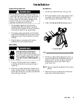
1.

Relieve pressure. Disconnect the fluid hose.

2.

Remove the nuts (19) and gasket retainer (29) and
gasket (15) from the kit needle (20). Leave the
large gasket (28) on the needle.

3.

Install the new gasket (15) and gasket retainer (29)
in the gun outlet. Torque to 190–210 in–lb (23–24
N.m).

4.

Guide the new needle (20) into the gun body.
Screw the nuts (19) onto the needle.

5.

Slide the extension tube (30) over the needle and
tighten securely onto the gun.

6.

Remove the nozzle adapter (21) from the exten-
sion. Install the metallic gasket (15) in the seat
cavity of the extension (30). Screw the original gun
seat (21) into the extension. Torque to 190–210
in–lb (23–24 N.m).

7.

Install the gasket (5) and screw on the nozzle
adapter (31). Install the spring (7) on the rear of
the needle.

8.

Before completing the assembly, adjust the
needle. See page 6.

WARNING

Proper needle adjustment is essential to be sure
the safety latch makes the gun inoperative when
engaged. Improper adjustment may allow the gun
to be triggered, even with the safety latch engaged,
resulting in serious injury, including fluid injection
and splashing in the eyes or on the skin.

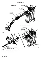
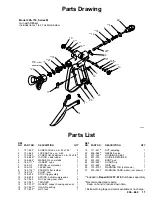
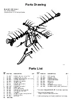
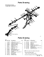
Dotted–line parts in this drawing indicate parts from
the original gun, Model 206–718 or 207–300. 
Solid line parts are supplied in the Kit 207–049.

0966

30

20

28

29

15

19

7

6

22

15

21

5

31

5

24

TIP, order separately

Model 207–049, Extension Kit
Includes items listed below.

REF
NO.

PART NO.

DESCRIPTION

QTY

5

166–969

WASHER, non–metallic

1

15

167–730

GASKET, copper, housing and seat 2

19

167–283

NUT, adjusting

2

20

207–134

NEEDLE, valve

1

28

167–284

GASKET, nylon

1

29

167–285

RETAINER, gasket

1

30

207–135

EXTENSION, gun; 37.5” (950 mm) lg1

31

207–136

ADAPTER, nozzle, 30

_

1

TORQUE TO
190–210  in–lb
(23–24 N.m)

Summary of Contents for HYDRA-MASTIC 206-718

Page 1: ...odel 206 718 Series M Standard Gun with Diffuser Model 207 300 Series J Standard Gun without Diffuser Model 207 127 Series K Pole Gun with Diffuser and 37 5 950 mm Extension NOTE Spray tip not include...

Page 2: ...condition and result in a fire or explosion and serious injury If there is any static sparking or you feel an electric shock while using this equipment stop spraying immediately Do not use the equipm...

Page 3: ...serious injury Fluid injected into the skin is a serious injury The injury may look like just a cut but it is a serious injury Get immediate medical attention Do not point the gun at anyone or at any...

Page 4: ...equipment D Use fluids and solvents which are compatible with the equipment wetted parts Refer to the Tech nical Data section of all equipment manuals Read the fluid and solvent manufacturer s warn i...

Page 5: ...ound the pump and all other equipment used or located in the spray area Also read FIRE OR EXPLOSION HAZARD on page 2 1 Check your local electrical code for detailed grounding instructions for your are...

Page 6: ...ing nut or hose end coupling to relieve pressure gradually then loosen completely Now clear the tip or hose obstruction WARNING INJECTION HAZARD To reduce the risk of serious injury whenever you are i...

Page 7: ...vent soaked brush to clean the spray tip and to keep fluid buildup from drying in and clogging the spray tip If the spray tip clogs while spraying release the spray gun trigger engage the safety latc...

Page 8: ...ustment is essential to be sure the safety latch makes the gun inoperative when engaged Improper adjustment may allow the gun to be triggered even with the safety latch engaged resulting in serious in...

Page 9: ...asket 15 Remove the needle 20 from the rear of the gun 7 Noting the number of full turns required to re move each one remove the two nuts from the needle one each 18 and 19 for Models 206 718 and 207...

Page 10: ...in lb 23 24 N m 28 29 TORQUE TO 190 210 in lb 23 24 N m 1 13 22 8 9 4 16 14 1 2 npsm m 1 13 22 8 9 4 16 14 1 2 npsm m A 24 5 21 20 TIGHTEN THIS SCREW FIRST TIGHTEN THIS SCREW FIRST 13 9 4 16 8 13 10...

Page 11: ...n 1 8 164 114 LEVER cam 1 9 164 116 PACKING flat leather 2 10 164 118 SHAFT cam 1 11 166 936 STOP trigger safety 1 12 166 938 SPRING helical compression 1 13 167 045 NUT packing cam shaft 2 14 167 047...

Page 12: ...ion 1 8 164 114 LEVER cam 1 9 164 116 PACKING flat leather 2 10 164 118 SHAFT cam 1 11 166 936 STOP trigger safety 1 12 166 938 SPRING helical compression 1 13 167 045 NUT packing cam shaft 2 14 167 0...

Page 13: ...KING flat leather 2 10 164 118 SHAFT cam 1 11 166 936 STOP trigger safety 1 12 166 938 SPRING helical compression 1 13 167 045 NUT packing cam shaft 2 14 167 047 TRIGGER 1 15 167 730 GASKET copper hou...

Page 14: ...0 in lb 23 24 N m 7 Install the gasket 5 and screw on the nozzle adapter 31 Install the spring 7 on the rear of the needle 8 Before completing the assembly adjust the needle See page 6 WARNING Proper...

Page 15: ...of the spray guns in this manual have been updated to reflect levels directed by ECO F4440 Technical Data Maximum Working Pressure 3000 psi 210 bar Fluid Orifice Size 0 17 in 4 32 mm dia Wetted Parts...

Page 16: ...set forth above The buyer agrees that no other remedy including but not limited to incidental or consequential damages for lost profits lost sales injury to person or property or any other incidental...

Reviews: