background image

Grounding 

12

312666P

Grounding

Check your local electrical code and propor-
tioner manual for detailed grounding instruc-
tions.

Ground the spray gun through connection to a 
Graco-approved grounded fluid supply hose.

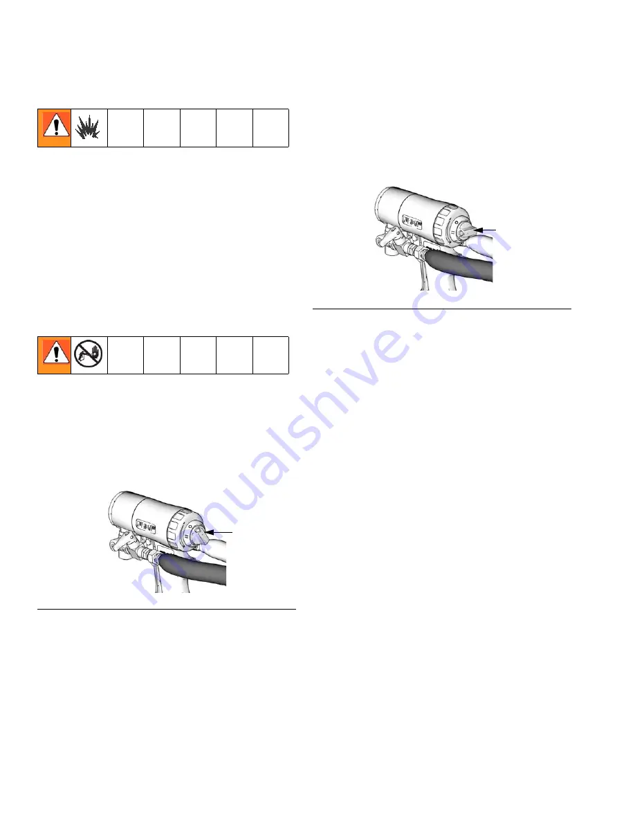
Piston Safety Lock

Engage piston safety lock whenever you stop 
spraying to avoid accidental triggering.

Engage

To engage piston safety lock, push knob in and 
turn clockwise. If engaged, gun will not actu-
ate.

Disengage

To disengage piston safety lock, push knob in 
and turn counterclockwise until it pops out. 
There will be a gap between knob and gun 
body.

F

IG

. 2

Engaged

TI11326a

F

IG

. 3

Disengaged

TI12240a

Summary of Contents for Fusion CS00F1

Page 1: ...foam and polyurea Not for use in explosive atmospheres 3500 psi 24 5 MPa 245 bar Maximum Fluid Working Pressure 80 130 psi 0 56 0 9 MPa 5 6 9 0 bar Air Inlet Pressure Range 200 F 94 C Maximum Fluid T...

Page 2: ...26 Clean or Replace Front Cover and Retainer 26 Clean Breather Plug 26 Clean Fluid Manifold 27 Adjust Fluid Valve Packings 27 Clean Mix Chamber Nozzle 28 Clean Passages 29 Clean Impingement Ports 29...

Page 3: ...scription 309572 Instructions Parts Manual English Solvent Flush Kits Part Description 309963 Instructions Parts Manual English 256566 Circulation Manifold Kit Part Description 313058 Instructions Par...

Page 4: ...SST CS02RD B RD0202 0 052 1 30 02 SST CS03RD B RD0303 0 060 1 50 03 SST FLOW RATE in gpm lpm PRESSURE in psi MPa bar 5 0 18 9 4 0 15 1 3 0 11 4 1 0 3 8 2 0 7 6 0 RD0101 01 WD 0101 RD0000 00 WD0000 500...

Page 5: ...0 038 0 97 CS00F6 B FL0000 0 029 0 70 00 FT0848 16 18 406 457 0 048 1 22 CS01F1 B FL0101 0 042 1 00 01 FT0424 8 10 203 254 0 024 0 61 CS01F2 B FL0101 0 042 1 00 01 FT0438 8 10 203 254 0 038 0 97 CS01F...

Page 6: ...iply gpm rate by 10 Example 2 gpm x 10 20 lb min FL0202 with FTXX48 tip FL2020 with FTXX24 tip Mix Chamber Pattern Diameter at 24 in 610 mm to Target in mm Equivalent Flow to Mix Chamber Size Referenc...

Page 7: ...n cause serious injury or death if splashed in the eyes or on skin inhaled or swallowed Read MSDS s to know the specific hazards of the fluids you are using Store hazardous fluid in approved container...

Page 8: ...not exceed the maximum working pressure or temperature rating of the lowest rated system component See Technical Data in all equipment manuals Use fluids and solvents that are compatible with equipmen...

Page 9: ...se Fitting under cover H Handle L Piston Safety Lock Flow Selector Knob M Gun Fluid Manifold N Mix Chamber Nozzle P Optional Fluid Inlets A Side Shown R ClearShot Liquid Cartridge S Fluid Inlet Swivel...

Page 10: ...moisture Always keep solvent con tainers closed when not in use Never use solvent on one side if it has been contaminated from the other side Always park pumps when you shutdown Always lubricate threa...

Page 11: ...hly clean Always clean the fluid inlet strainers after flushing Check with your material manufacturer for chemical compatibility Most materials use ISO on the A side but some use ISO on the B side Epo...

Page 12: ...ly hose Piston Safety Lock Engage piston safety lock whenever you stop spraying to avoid accidental triggering Engage To engage piston safety lock push knob in and turn clockwise If engaged gun will n...

Page 13: ...ure fluid valves A and B are closed before turning front cover retainer C Loss of Air Pressure In event of loss of air pressure gun will con tinue to spray To shut off gun do one of the following Push...

Page 14: ...id manifold check valves 4 Engage piston safety lock page 12 5 Install ClearShot Liquid cartridge See ClearShot Liquid Cartridge Installa tion Removal page 23 6 Connect gun air whip hose V air valve W...

Page 15: ...12 12 Turn on proportioner 13 Open B RESIN fluid valve Then open A ISO fluid valve 14 Disengage piston safety lock page 12 15 Test spray onto cardboard Adjust pressure and temperature to get desired r...

Page 16: ...ease use a half shot maximum 5 Replace front cover U and front cover retainer C Grease gun daily to prevent two compo nent curing and keep fluid passages clean Purge air carries grease mist through ai...

Page 17: ...ion Do not disconnect gun air supply until fluid pres sure is relieved FIG 18 TI11326a TI11327a A W FIG 19 FIG 20 Fluid in the hose and proportioner is still under pressure Follow the Pressure Relief...

Page 18: ...l inlets P 4 Apply thread sealant to plugs 1e elbows 35 and male threads of fluid valve assemblies Install elbows 35 in optional inlets facing down Install fluid valve assemblies in elbows Be sure to...

Page 19: ...or details of tool 7 Reassemble in reverse order a Insert mix chamber 14 from rear of fluid housing b Tighten A and B side seals on fluid housing c Assemble o ring 47 tip 21 and tip retainer 46 to fro...

Page 20: ...27 Change Variable Flow Adjustment Knob 1 Turn air valve W OFF 2 Turn flow selector knob to variable flow position See FIG 27 The variable flow feature is designed to provide immediate adjustment betw...

Page 21: ...set to the variable flow position See FIG 27 5 Test spray pattern on cardboard Repeat steps 1 through 6 until desired spray pat tern is reached FIG 28 The variable flow adjustment knob cannot be adjus...

Page 22: ...Variable Flow 22 312666P...

Page 23: ...wise to lock it into gun handle 5 Turn air valve ON and prime ClearShot Liq uid dosing pump a Trigger gun 20 times to prime dosing pump b Trigger gun onto cardboard to see dosed ClearShot Liquid 6 Res...

Page 24: ...Relief Procedure page 17 2 Turn air valve W OFF 3 Push in and turn cartridge 1 4 turn counter clockwise viewed from bottom 4 Pull cartridge out of gun handle Troubleshooting For ClearShot Liquid cart...

Page 25: ...an with accessory gun cover page 55 Applying a light coat of lubricant will make cleaning easier As Needed 1 Clean Outside of Gun page 26 2 Clean Mix Chamber Nozzle page 28 a minimum of once a day 3 C...

Page 26: ...utside of gun with compatible sol vent Use N Methylpyrrolidone NMP Dyna solve CU 6 Dzolv or an equivalent to soften cured material Clean or Replace Front Cover and Retainer Soak front cover retainer C...

Page 27: ...g them from fluid manifold 4 Clean or replace fluid screens See Acces sories page 55 5 Carefully inspect o rings and fluid screen surfaces Replace if worn or damaged 6 Liberally lubricate o rings and...

Page 28: ...ate size drill bit to clean mix cham ber nozzle N Table 1 Nozzle Drill Bit Sizes FIG 39 TI11326a FIG 40 Round Spray Flat Spray Mix Chamber Drill Size in mm Mix Chamber Drill Size in mm RD2020 58 042 1...

Page 29: ...n an accessory kit Order kit 256526 for ClearShot Handle Drill Kit see Accesso ries page 55 Clean Impingement Ports 1 Follow Pressure Relief Procedure page 17 2 Disconnect air D and remove fluid mani...

Page 30: ...air D Return gun to service Some mix chambers have counter bored holes and require two drill sizes to clean impingement ports completely FIG 42 TI12097a Impingement Port IP CB IP TI3533a Mix Chambers...

Page 31: ...slowly Plugged breather plug 9 Clean Breather Plug page 26 Damaged piston o rings 4a 4c Replace See Piston page 42 Dirty air valve or damaged o rings 15 Clean air valve or replace o rings See Air Val...

Page 32: ...ose valves first Fluid mist from mix chamber Damaged side seals 42 43 Replace See Mix Chamber and Side Seal Assemblies page 38 Damaged side seal o rings 42d 42e Replace See Mix Chamber and Side Seal A...

Page 33: ...place See ClearShot Liquid Cartridge Installation Removal page 23 Damaged or cracked cartridge Replace See ClearShot Liquid Cartridge Installation Removal page 23 Damaged dosing piston Repair See Pist...

Page 34: ...etriggered Air Purging Mix chamber 14 moves forward shutting off fluid flow Impingement ports IP open to air chamber AC allowing purge air to flow through mix chamber nozzle N See Shutdown page 16 for...

Page 35: ...Theory of Operation 312666P 35 Cutaway View TI12091a 20 19 42 14 3 45 44 6 5 15 17 15 16 13 9 23 1 Hose Manifold Assy see page 48 4 Piston Assy see page 44 2 Fluid Housing Assy see page 44...

Page 36: ...5 Remove front cover U 6 Turn fluid housing F 1 4 turn counter clockwise to disengage slots Remove fluid housing 7 Inspect fluid housing o rings for wear or damage Replace if necessary Do not lubricat...

Page 37: ...socket of piston assembly 4 3 Push fluid housing F flush to handle 4 Turn fluid housing 1 4 turn clockwise to engage slots 5 Replace front cover U 6 Screw on front cover retainer C Proper attachment...

Page 38: ...driver to remove side seal assemblies 42 43 7 Push on front of mix chamber 14 to loosen Pull mix chamber out rear of fluid housing F Inspect for damage and Clean Impingement Ports page 29 FIG 49 FIG 5...

Page 39: ...ly inspect side seal assembly o rings and surfaces Replace worn or damaged parts Liberally lubricate o rings 42d 42e and reassemble 11 Line up tabs on seal 42c and seal housing 42a insert seal into ho...

Page 40: ...3 Liberally lubricate and reinstall side seal assemblies 42 43 Use hex nut driver to tighten 14 Attach Front End page 37 15 Connect air and trigger the gun a few times to check for leaks If purge air...

Page 41: ...t head screwdriver 7 Clean and inspect all parts Thoroughly inspect o rings 44e 44f Press on ball 44b to test check valve for proper move ment and spring action Replace individual check valve parts as...

Page 42: ...o ring 4c and shaft o rings 4a 6 Remove dosing piston a Use supplied screw driver to remove spiral retaining ring 4g b Use screw driver to push dosing piston 4e out back of piston 4b through access h...

Page 43: ...onnect air Return gun to service Air Valve 1 Follow Pressure Relief Procedure page 17 2 Disconnect air D and remove fluid mani fold M 3 Unscrew air valve plug 13 and remove spring 16 Using a small dia...

Page 44: ...5 N m 1 2 3 4 Seal Assembly 42 Detail Check Valve 44 Detail TI12104a TI12105a TI12098b 42d 42c 42b 42e 42a 44e 44d 44c 44b 44a 44f 3 5 6 7 8 9 2c 2b 19 13 14 16 17 15 20 4a 4c 4b 4d 4e 4f 4g 32 34 23...

Page 45: ...k of 6 1 4d O RING 3 4e 257424 PISTON dosing assy includes 4d and 4f 1 4f 257426 O RING pack of 6 1 4g 121642 RING retaining internal spiral 1 5 15B209 TRIGGER 1 6 192272 PIN pivot 1 7 203953 SCREW 10...

Page 46: ...s 42d 1 42d 256467 O RING pack of 6 1 42e 256468 O RING pack of 6 1 43 256463 KIT seal b side assy includes 42 and 43a 43e 1 43a HOUSING seal side 1 43b 256923 SPRING compression 1 43c 256464 SEAL sid...

Page 47: ...CS00F2 Order Kit FL0000 CS00F3 Order Kit FL0000 CS00F4 Order Kit FL0000 CS00F5 Order Kit FL0000 CS00F6 Order Kit FL0000 CS01F1 Order Kit FL0101 CS01F2 Order Kit FL0101 CS01F3 Order Kit FL0101 CS01F4 O...

Page 48: ...plied Tools Detail Views Apply lubricant to seals Apply sealant to threads 1 3 2 Hose Fluid Manifold 1 Detail TI12106a TI3870a TI12107a TI12108a 36 37 1a 1b 1d 1g 1j 1k 1e 1h 1f 40 14 47 21 46 25 27 1...

Page 49: ...2 58 1 00 0 020 76 0 50 0 060 53 1 50 RD0000 8 203 0 052 55 1 30 0 029 69 0 70 0 060 53 1 50 RD0101 11 279 0 060 53 1 50 0 042 58 1 00 N A N A RD0202 12 305 0 070 50 1 75 0 052 55 1 30 N A N A RD0303...

Page 50: ...2 35 0 020 76 0 50 0 060 53 1 50 FL0000 246360 0 094 3 32 2 35 0 029 69 0 70 0 060 53 1 50 FL0101 246360 0 094 3 32 2 35 0 042 58 1 00 N A N A FL0202 246360 0 094 3 32 2 35 0 052 55 1 30 N A N A RD 0...

Page 51: ...ngs Includes installation tools and side seal springs Kit Reference Number 1b 2b 2c 2d 3a 4a 4c 42d 43d 42e 43e 44e 45e 44f 45f 256490 Complete Kit 2 1 1 1 1 2 1 2 2 2 2 256467 Side Seal 6 256468 Side...

Page 52: ...0 in O ring Repair Kits on page 51 for the quantity of each Check Valve Filter Screen Kits Kits include 10 filter screens The 80 mesh filter screen is standard with gun 4c 2b 42e 43e 3a 2d 2c 4a 42d 4...

Page 53: ...18 246623 3 32 0 116 2 90 246810 3 7 64 0 109 2 77 246813 3 39 0 099 2 51 246624 3 3 32 0 094 2 39 246812 3 43 0 089 2 26 246625 3 44 0 086 2 18 248639 6 2 15 mm 0 085 2 15 249114 6 45 0 082 2 08 246...

Page 54: ...See Clean Passages page 29 246629 6 58 0 042 1 07 246808 6 60 0 040 1 02 248640 6 61 0 039 0 99 248618 6 63 0 037 0 94 248891 6 66 0 033 0 84 246807 6 67 0 032 0 81 246630 6 69 0 029 0 74 248892 6 70...

Page 55: ...lubricant MSDS sheet available at www graco com Grease Cartridge for Gun Shutdown 248280 Cartridge 3 oz 10 Specially formulated low viscosity grease flows easily through gun passages to prevent two c...

Page 56: ...fold with individual A and B shutoff valves and air regulator See manual 309963 Tip Cleanout Tool 15D234 Designed to fit CeramTip internal dome and flat tip slits Circulation Manifold 256566 Attach to...

Page 57: ...0 F 94 C Air Inlet Size 1 4 npt Quick Disconnect Nipple A Component ISO Inlet Size 5 JIC 1 2 20 UNF B Component Resin Inlet Size 6 JIC 9 16 18 UNF Sound Pressure 75 27 dB A using RD0202 at 100 psi 0 7...

Page 58: ...f the equipment does not disclose any defect in material or workmanship repairs will be made at a reasonable charge which charges may include the costs of parts labor and transportation THIS WARRANTY...

Reviews: