background image

Repair

Update

Update

Update ADM

ADM

ADM Software

Software

Software

1. Turn the main power switch OFF.

2. Open the top and bottom door latches to the

electric cabinet.

3. Open the electrical cabinet. Use a Phillips

screwdriver to loosen the four ADM
mounting screws on the inside of the cabinet
door.

4. Lift the ADM up and pull it away from the

Reactor to unseat the mounting screws. For
easy reassembly, leave the loosened screws
attached to the ADM.

5. Remove the token access panel on the back

of the ADM.

6. Insert and press the software upgrade token

firmly into the slot.

NOTE:

NOTE:

NOTE: There is no preferred orientation of
the token.

7. Close the electrical cabinet.

8. Turn the main power switch ON.

NOTICE

NOTICE

NOTICE

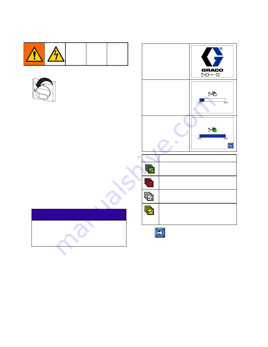
A status is shown while software is
updating to indicate progress. To prevent
corrupting the software load, do not
remove the token until the status screen
disappears.

NOTE:

NOTE:

NOTE: When the ADM display turns on, you
may see the following screens:

First:

First:

First:

Software is checking
which modules will
take the available
updates.

Second:

Second:

Second:

Status of the
update with
approximate time
until completion.

Third:

Third:

Third:

Updates are
compete. Icon
indicates update
success/failure. See
the following table.

Icon

Icon

Icon

Description

Description

Description

Update successful

Update unsuccessful

Update complete, no changes
necessary

Modules were updated or did
not require an update; however,
one or more modules need to be
updated manually with a token.

9. Press

to continue to the operation

screen.

10. Turn the main power switch OFF.

11. Remove the software update token.

12. Replace the token access panel.

13. Open the electrical cabinet, remount the

ADM, and fully tighten the four mounting
screws.

14. Close the lock and the cabinet door with the

door latches.

74

334946J

Summary of Contents for FHH074

Page 1: ...gs coatings coatings Not Not Not for for for outdoor outdoor outdoor use use use For For For professional professional professional use use use only only only Not Not Not approved approved approved for for for use use use in in in explosive explosive explosive atmospheres atmospheres atmospheres or or or hazardous hazardous hazardous classified classified classified locations locations locations I...

Page 2: ...ace RTD 64 Repair Heated Hose 65 Repair Fluid Temperature Sensor FTS 67 Calibration Procedure 68 Repair Circuit Breaker Module 69 Transformer Primary Check 70 Transformer Secondary Check 70 Replace Transformer 71 Replace Power Supply 71 Replace Surge Protector 72 Replace Temperature Control Module TCM 72 Replace HCM 73 Replace ADM 73 Software Update Procedure 73 Update ADM Software 74 Parts 75 Eli...

Page 3: ...s injury or death if splashed in the eyes or on skin inhaled or swallowed Read Safety Data Sheet SDS for handling instructions and to know the specific hazards of the fluids you are using including the effects of long term exposure When spraying servicing equipment or when in the work area always keep work area well ventilated and always wear appropriate personal protective equipment See Personal ...

Page 4: ...ON EXPLOSION HAZARD HAZARD HAZARD Flammable fumes such as solvent and paint fumes in work work work area area area can ignite or explode Paint or solvent flowing through the equipment can cause static sparking To help prevent fire and explosion Use equipment only in well ventilated area Eliminate all ignition sources such as pilot lights cigarettes portable electric lamps and plastic drop cloths p...

Page 5: ...lure to follow this warning can result in death serious injury or property damage Do not use 1 1 1 trichloroethane methylene chloride other halogenated hydrocarbon solvents or fluids containing such solvents Do not use chlorine bleach Many other fluids may contain chemicals that can react with aluminum Contact your material supplier for compatibility PLASTIC PLASTIC PLASTIC PARTS PARTS PARTS CLEAN...

Page 6: ...nuine manufacturer s replacement parts only Do not alter or modify equipment Alterations or modifications may void agency approvals and create safety hazards Make sure all equipment is rated and approved for the environment in which you are using it Use equipment only for its intended purpose Call your distributor for information Route hoses and cables away from traffic areas sharp edges moving pa...

Page 7: ... inhalation of isocyanate mists vapors and atomized particulates everyone in the work area must wear appropriate respiratory protection Always wear a properly fitting respirator which may include a supplied air respirator Ventilate the work area according to instructions in the fluid manufacturer s SDS Avoid all skin contact with isocyanates Everyone in the work area must wear chemically impermeab...

Page 8: ...de Moisture Moisture Moisture Sensitivity Sensitivity Sensitivity of of of Isocyanates Isocyanates Isocyanates Exposure to moisture such as humidity will cause ISO to partially cure forming small hard abrasive crystals that become suspended in the fluid Eventually a film will form on the surface and the ISO will begin to gel increasing in viscosity NOTICE NOTICE NOTICE Partially cured ISO will red...

Page 9: ...Instructions Parts 3A1907 Remote Display Module Kit Instructions Parts 332735 Air Manifold Kit Instructions Parts 3A3010 Caster Kit Instructions Parts 333276 Graco InSite Kit Instructions Parts 3A3084 Elite Kit Instructions Part Accessories Accessories Accessories Kit Kit Kit Number Number Number Description Description Description 24U315 Air Manifold 4 outlets 17G340 Caster Kit 17F837 Inlet Senso...

Page 10: ...kage Package Package 6 Gun Part APH031 246102 AHH031 246102 APH032 246102 AHH032 246102 APH131 246102 AHH131 246102 APH132 246102 AHH132 246102 Fusion Fusion Fusion CS CS CS Package Package Package 6 Gun Part CSH031 CS02RD CHH031 CS02RD CSH032 CS02RD CHH032 CS02RD CSH131 CS02RD CHH131 CS02RD CSH132 CS02RD CHH132 CS02RD Probler Probler Probler P2 P2 P2 Package Package Package 6 Gun Part P2H031 GCP2...

Page 11: ...4 246103 APH143 246103 AHH143 246103 APH144 246103 AHH144 246103 Fusion Fusion Fusion CS CS CS Package Package Package 6 Gun Part CSH043 CS02RD CHH043 CS02RD CSH044 CS02RD CHH044 CS02RD CSH143 CS02RD CHH143 CS02RD CSH144 CS02RD CHH144 CS02RD Probler Probler Probler P2 P2 P2 Package Package Package 6 Gun Part P2H043 GCP2R2 PHH043 GCP2R2 P2H044 GCP2R2 PHH044 GCP2R2 P2H143 GCP2R2 PHH143 GCP2R2 P2H144...

Page 12: ...on Fusion AP AP AP Package Package Package 6 Gun Part APH045 246103 AHH045 246103 APH046 246103 AHH046 246103 APH145 246103 AHH145 246103 APH146 246103 AHH146 246103 Fusion Fusion Fusion CS CS CS Package Package Package 6 Gun Part CSH045 CS02RD CHH045 CS02RD CSH046 CS02RD CHH046 CS02RD CSH145 CS02RD CHH145 CS02RD CSH146 CS02RD CHH146 CS02RD Probler Probler Probler P2 P2 P2 Package Package Package ...

Page 13: ...53 246103 AHH153 246103 APH156 246103 AHH156 246103 Fusion Fusion Fusion CS CS CS Package Package Package 6 Gun Part CSH053 CS02RD CHH053 CS02RD CSH056 CS02RD CHH056 CS02RD CSH153 CS02RD CHH153 CS02RD CSH156 CS02RD CHH156 CS02RD Probler Probler Probler P2 P2 P2 Package Package Package 6 Gun Part P2H053 GCP2R2 PHH053 GCP2R2 P2H056 GCP2R2 PHH056 GCP2R2 P2H153 GCP2R2 PHH153 GCP2R2 P2H156 GCP2R2 PHH15...

Page 14: ...I UL Std 499 Certified to CAN CSA Std C22 2 No 88 Fusion Fusion Fusion AP AP AP Package Package Package 6 Gun Part APH062 246101 AHH062 246101 APH162 246101 AHH162 246101 Probler Probler Probler P2 P2 P2 Package Package Package 6 Gun Part P2H062 GCP2R1 PHH062 GCP2R1 P2H162 GCP2R1 PHH162 GCP2R1 24K241 24K241 24Y241 24K241 Heated Heated Heated Hose Hose Hose 50 50 50 ft ft ft 15 15 15 m m m Qty 1 Qt...

Page 15: ...on Fusion Fusion AP AP AP Package Package Package 6 Gun Part APH074 246103 AHH074 246103 APH076 246103 AHH076 246103 APH174 246103 AHH174 246103 APH176 246103 AHH176 246103 Probler Probler Probler P2 P2 P2 Package Package Package 6 Gun Part P2H074 GCP2R2 PHH074 GCP2R2 P2H076 GCP2R2 PHH076 GCP2R2 P2H174 GCP2R2 PHH174 GCP2R2 P2H176 GCP2R2 PHH176 GCP2R2 24K241 24K241 24K241 24K241 24Y241 24Y241 24Y24...

Page 16: ...tional Error Error Error Description Description Description Alarms Alarms Alarms A parameter critical to the process has reached a level requiring the system to stop The alarm needs to be addressed immediately Deviations Deviations Deviations A parameter critical to the process has reached a level requiring attention but not sufficient enough to stop the system at this time Advisories Advisories ...

Page 17: ...re page 68 Short circuit in heater wiring Check wiring for touching wires A4DA Heater A High Current A Bad Heater Confirm resistance of heater Heater resistance should be 18 21 Ω for each heater element 9 12 Ω combined for 10 kW systems 6 8 Ω for 15 kW systems and 4 6 Ω for 20 kW systems If out of tolerance replace heater element Short circuit in heater wiring Check wiring for touching wires A4DB ...

Page 18: ...ected Current Hose Shorted TCM If error cannot be cleared or regenerates consistently replace module Tripped circuit breaker Visually check circuit breaker for a tripped condition A8DA Heater A No Current A Loose broken connection Check heater wiring for loose wires Tripped circuit breaker Visually check circuit breaker for a tripped condition A8DB Heater B No Current B Loose broken connection Che...

Page 19: ...2 H XP2 3 H XP3 4 No 24 VDC supply to module Green light on each module should be lit If green light is not lit check to make sure each CAN cable connection is tight Verify the power supply is outputting 24 VDC If not check power supply wiring If wiring is okay replace the power supply CACM HCM HCM Communica tion Error Loose or broken CAN cable Check the CAN cables running between GCA modules and ...

Page 20: ...nica tion Error Loose or broken CAN cable Check the CAN cables running between GCA modules and tighten of needed If the problem still persists move each cable around the connector and watch the flashing yellow light on the GCA modules If the yellow light stops flashing replace the CAN cable Mix chamber too large for system selected Use mix chamber rated for system Ensure the system has chemical an...

Page 21: ...d USB down load uploads are disabled Enable USB down load uploads on the Advanced Setup screen before inserting a USB drive H2MA Heater A Low Frequency A Line frequency is below 45 Hz Ensure line frequency of incoming power is between 45 and 65 Hz H2MB Heater B Low Frequency B Line frequency is below 45 Hz Ensure line frequency of incoming power is between 45 and 65 Hz H2MH Hose Low Frequency Hose...

Page 22: ...e value on the System Setup screen is at an acceptable maximum pressure to prevent unnecessary alarms and abort dispenses Out of material Fill the tanks with material Fluid leaking from heater inlet rupture disk Check if heater and PRESSURE RELIEF SPRAY valve are plugged Clear Replace rupture disk Do not replace with a pipe plug P0AX HCM Pressure Imbalance A High Feed system defective Check feed p...

Page 23: ... low pressure alarm level defined on the System Setup screen is acceptable Inlet pressure lower than defined value Ensure that inlet pressure to the pump is sufficient P1FB HCM Low Inlet Pressure B Value defined too high Ensure that the low pressure alarm level defined on the System Setup screen is acceptable Inlet pressure lower than defined value Ensure that inlet pressure to the pump is suffici...

Page 24: ...nd H XP3 Ensure dial on HCM is set to position 3 for H XP2 or 4 for H XP3 System pressurized before allowing heat to reach setpoint Pressure in the hose and pumps will increase as the system heats up Turn on heat and allow all zones to reach the temperature setpoint before turning on the pumps Bad pressure transducer Verify the ADM pressure reading and the analog gauges at the manifold P4BX HCM Hi...

Page 25: ... from the HCM connectors 6 and 7 Reverse A and B connections and check if the errors follows If the error follows the transducer replace the pressure transducer Loose bad connection Check to ensure the pressure transducer is properly installed and all wires are properly connected P6BX HCM Pressure Sensor Error B Bad sensor Check if the error follows the transducer Disconnect transducer cables from...

Page 26: ...ws the sensor replace the inlet sensor Inlet sensors not installed If inlet sensors are not installed inlet sensors should be disabled on the System Setup screen Loose bad connection Check to ensure inlet sensor is properly installed and all wires are properly connected P6FB HCM Pressure Sensor Error Inlet B Bad sensor Check if the error follows the inlet sensor Disconnect inlet sensor cables from...

Page 27: ... not replace with a pipe plug P7AX HCM Pressure Imbalance A High Feed system defective Check feed pump and hoses for blockage Check that feed pumps have correct air pressure Pressure difference between A and B material is greater than the defined value Ensure material flow is equally restricted on both material lines Pressure imbalance is defined too low Ensure that the pressure imbalance value on...

Page 28: ...he resin pump and replace if necessary Fluid leak between resin pump and meter Inspect the fluid lines for resin leak Damaged resin recirculation valve Replace the resin valve Damaged resin flow meter Replace the resin meter Resin material drum is empty Replace the resin drum R4D0 ADM High Ratio Low Flow B Cavitation on resin pump Increase the resin feed pump pressure Damaged ISO flow meter Replac...

Page 29: ...ires Flow is too high at current setpoint Use a smaller mix chamber that is rated for the unit in use If recirculating decrease flow or decrease temperature setpoint Bad RTD or bad RTD placement against heater Swap A and B heater output cables and RTD cables and see if issue follows If so replace RTD Bad heater element Confirm resistance of heater Heater resistance should be 9 12 Ω for 10 kW syste...

Page 30: ...se setpoint T3CH Hose Hose Cutback Hose current has been reduced because hose has been drawing current for an extended period Hose FTS is in a colder environment than the rest of the hose Expose FTS to the same environment as the rest of the hose High ambient temperature Ensure ambient temperature is below 120 F 48 C before using the system Enclosure fan not operating Ensure fan in electrical encl...

Page 31: ...ad RTD or bad RTD placement against heater Swap A and B heater output cables and RTD cables and see if issue follows If so replace RTD T4DB Heater B High Temperature B Flow too high for temperature setpoint causing temperature overshoots when gun is de triggered Use a smaller mix chamber that is rated for the unit in use Hose portion exposed to an excessive heat source like hot sun or coiled hose ...

Page 32: ... overtemperature switch cable connection If heater is not actually over temperature check all wiring and connections between the TCM and the overtemperature switches T4EA Heater A High Temperature Switch A Overtemperature switch failed in the open position Replace the overtemper ature switch Overtemperature switch sensed a fluid temperature above 230 F 110 C Heater was delivered too much power cau...

Page 33: ...T6DB Heater B Sensor Error B Bad RTD Switch the RTD with another and see if the error message follows the RTD Replace RTD if the error follows the RTD T6DH Hose Sensor Error Hose Disconnected or shorted RTD cable in hose or bad FTS Expose each hose RTD connection to check and retighten any loose con nector Measure hose RTD cable and FTS conti nuity See Repair Heated Hose page 65 Order RTD Test kit...

Page 34: ...se Control Modes T6DT TCM Sensor Error TCM Shorted A or B Heater RTD If the error still occurs with the hose FTS unplugged one of the heater RTDs is bad Unplug the A or B RTD from the TCM If unplugging an RTD fixes the T6DT error replace the RTD Bad RTD or bad RTD placement against heater Swap A and B heater output cables and RTD cables and see if issue follows If so replace RTD Bad heater element...

Page 35: ...Temperature Rise Hose Started spraying before heater reached operating temperature Wait until operating temperature has been reached before spraying or recirculating V1IT TCM Low Voltage CAN Bad 24 VDC power supply Check voltage of power supply Voltage should be 23 25 VDC If out of tolerance replace power supply V2IT TCM Low Voltage CAN Bad 24 VDC power supply Check voltage of power supply Voltage...

Page 36: ...r is between 195 and 264 VAC V3MH TCM High Voltage Hose Incoming line voltage is too high Ensure incoming system power is wired properly Verify voltage at each circuit breaker is between 195 and 264 VAC V4IT TCM High Voltage CAN Bad 24 VDC power supply Check voltage of power supply Voltage should be 23 25 VDC If out of tolerance replace power supply V4MA TCM High Voltage A Incoming line voltage is...

Page 37: ... language file failed to upload Perform normal USB download and use the new disptext txt file to upload the custom language Hose section removed or replaced without re calibration Re calibrate the hose Follow the Calibration Procedure page 68 Z1DH Hose Low Resistance Hose Wire Hose wire temperature is too low Ensure hose wire temperature is above 4 F 20 C Hose section added or replaced without re ...

Page 38: ...s from the last time the motor was turned off to reduce the chance of the motor overheating PROBLEM PROBLEM PROBLEM CAUSE CAUSE CAUSE SOLUTION SOLUTION SOLUTION Loose connections and or contactor CT01 is not closing Check wiring between the following components HCM and contactor CT01 HCM and fuses F11 F12 Damaged HCM Replace HCM Loose connections and or contactor CT01 is closing Check wiring betwe...

Page 39: ...allow for manual counterclockwise rotation of hydraulic pump Turn fan pulley by hand Verify oil flow by removing oil filter to see flow into filter manifold Reinstall oil filter Do NOT operate unit without a properly installed oil filter Screeching noise is characteristic of cavitation and is normal at initial startup for a maximum of 30 seconds If noise continues longer than 30 seconds press to s...

Page 40: ...es to determine which pump is losing pressure 2 Determine in which direction the pump has stalled by observing which directional icon is displayed on the ADM Home screen See Table 1 3 Repair the valve See pump manual Restriction at the gun Clean the gun see your separate gun manual Increase fluid supply to proportioning pump Use 2 1 supply pump Use minimum 3 4 in 19 mm ID supply hose as short as p...

Page 41: ...heater and PRESSURE RELIEF SPRAY valve SA or SB are plugged Clear Replace rupture disk with a new one do not replace with a pipe plug No pressure on one side Inadequate feed pump pressure Check feed pump pressure and adjust to 100 psi 0 7 MPa 7 bar minimum NOTE NOTE NOTE Table 1 is related to troubleshooting problem Proportioning pump does not hold pressure when stalled Table Table Table 1 1 1 Det...

Page 42: ...off confirm that the indicating lights on the body of each proximity switch 211 turns on when a metallic item such as the shaft of a screwdriver is placed on the face of each switch c If the indicating lights turn on the proximity switches its wiring and the HCM are likely operating correctly proceed to step 2 If the indicating lights do not turn on proceed to step 6 2 Confirm the proximity switch...

Page 43: ...n position position Pump Pump Pump driving driving driving right right right away away away from from from park park park position position position ADM indicates Indicator light on directional valve cover Left arrow labeled b Right arrow labeled a Last proximity switch triggered Right side proximity switch Left side proximity switch Terminals in directional valve energized Terminals associated wi...

Page 44: ...es not reach temperature If Hose Resistance Mode is enabled the calibration factor may be inaccurate Re calibrate the hose Follow the Calibration Procedure page 68 A and B setpoints too low Increase A and B setpoints Hose is designed to maintain temperature not to increase it Ambient temperature is too cold Increase A and B setpoints to increase fluid temperature and keep it steady Flow too high U...

Page 45: ...onnectors are clean Unplug and re plug FTS wires along length of hose cleaning off any debris FTS not installed correctly FTS should be installed close to end of hose in same environment as gun Verify FTS installation see Repair Fluid Temperature Sensor FTS page 67 Erratic hose temperature Missing or damaged insulation around FTS causing the hose heat to be ON constantly Make sure the hose bundle ...

Page 46: ...tpoints Hose designed to maintain temperature not increase temperature Hose temperature setpoint too low Check Increase if necessary to maintain heat Flow too high Use smaller mix chamber Decrease pressure Low current FTS not installed Install FTS see operation manual Hose heat zone not turned on long enough to reach setpoint Allow hose to heat up or preheat fluid Loose hose electrical connections...

Page 47: ...ADM for error codes Primary Heater s does not heat Signal failure from RTD Check ADM for error codes Confirm RTD cabling is properly connected and not damaged Replace RTD Dirty RTD connections Examine RTD cables connected to TCM Confirm RTDs are not plugged into opposite heat zone Unplug and re plug RTD connectors Unplug and re plug RTD connectors Ensure RTD tip contacts the heater element RTD not...

Page 48: ...of the proportioner Re route the feed hoses to a lower height Purge air from the system Refer to your ratio monitor manual for instructions The material ratio is significantly offset from 1 1 Air is trapped in the system between the feed pumps and the heated hose Place the heated hose on flat ground Spray material into a waste container until all air has left the system Increase the feed pump pres...

Page 49: ...elief Procedure when you stop spraying and before cleaning checking or servicing equipment The Fusion AP gun is shown 1 Press to stop the pumps 2 Turn off all heat zones 3 Relieve pressure in gun and perform gun shutdown procedure See gun manual 4 Close gun fluid inlet valves A and B 5 Shut off feed pumps and agitator if used 6 Route fluid to waste containers or supply tanks Turn PRESSURE RELIEF S...

Page 50: ...ss to park the Component A and Component B pumps The park operation is complete when green dot goes out Verify the park operation is complete before moving to next step 5 Press to deactivate the system 6 Turn off the air compressor air dryer and breathing air 7 Turn the main power switch OFF To prevent electric shock do not remove any covers or open the electrical enclosure door while the power is...

Page 51: ...e compatible with common solvents Use only moisture free solvents To flush feed hoses pumps and heaters separately from heated hoses set PRESSURE RELIEF SPRAY valves SA SB to PRESSURE RELIEF CIRCULATION Flush through bleed lines N To flush entire system circulate through gun fluid manifold with manifold removed from gun To prevent moisture from reacting with isocyanate always leave the system fill...

Page 52: ...Before Before Beginning Beginning Beginning Repair Repair Repair NOTICE NOTICE NOTICE Proper system setup startup and shutdown procedures are critical to electrical equipment reliability The following procedures ensure steady voltage Failure to follow these procedures will cause voltage fluctuations that can damage electrical equipment and void the warranty 1 Flush if necessary See Flushing page 5...

Page 53: ... and screw tool into left clevis pin 219 Pull clevis pin out of clevis 117 4 Use hex key to remove four socket head cap screws 203 from left proportioning pump 202 Remove left proportioning pump 5 Remove lube cylinder 205 6 Screw pin removal tool 296607 into right clevis pin 219 Pull clevis pin out of clevis 117 7 Use hex key to remove four socket head cap screws 203 on right proportioning pump 20...

Page 54: ...ions 1 Close the fluid inlet valve on the y strainer inlet and shut off the appropriate feed pump This prevents material from being pumped while cleaning the screen 2 Place a container under the strainer base to catch drain off when removing the strainer plug C 3 Remove the screen A from the strainer manifold Thoroughly flush the screen with compatible solvent and shake it dry Inspect the screen N...

Page 55: ...e clevis 317 to disconnect the pump from the hydraulic cylinder 201 Remove the four screws 203 holding the pump to the spacers 313 of the cylinder Take the pump assembly to a workbench 1 Torque to 200 in lb 22 6 N m 4 Disconnect the A ISO side pump inlet line the inlet y strainer and hard tube 55 Use the pin extractor tool 101 to remove the pin 213 which disconnects the pump from the hydraulic cyl...

Page 56: ...e housing with compatible solvent 9 Reinstall the gears a Place the gear with the magnets MG on the left pin of the housing NOTE NOTE NOTE The gear with the magnets MG must be installed on the left side or the meter will not function Install the gears as shown b Position the gears perpendicular 90 to each other and install the rounded bottom RB of the gear into the housing NOTE NOTE NOTE Turn the ...

Page 57: ... 4 When the reservoir is flushed clean fill with fresh lubricant 5 Thread the reservoir onto the cap assembly and place it in the bracket 6 Push the larger diameter supply ST tube approximately 1 3 of the way into the reservoir 7 Push the smaller diameter return tube RT into the reservoir until it reaches the bottom NOTE NOTE NOTE The return tube must reach the bottom of the reservoir to ensure th...

Page 58: ...WI ISO Grade 46 synthetic BP Oil International Energol HLP HM ISO Grade 46 Carl Bechem GmbH Staroil HVI 46 Castrol Hyspin AWS 46 Chevron Rykon AW ISO 46 Exxon Humble Hydraulic H ISO Grade 46 Mobil Mobil DTE 25 ISO Grade 46 Shell Shell Tellus ISO Grade 46 Texaco Texaco AW Hydraulic ISO Grade 46 Note Do not mix mineral based and synthetic hydraulic oils Completely drain oil from reservoir and pump p...

Page 59: ...See Electrical Schematics page 105 Close the electrical enclosure door 3 Remove mounting bolts from the bottom frame and move the system away from the wall Figure 2 4 Remove upper bolts 3 Tilt the electrical enclosure down to gain access to the motor cover 5 Remove motor and belt covers 123 131 132 Lift cover 132 and loosen the blue bracket 131 fasteners Lift the blue bracket 133 off of the fasten...

Page 60: ...tion Installation Installation 1 Place the motor on the unit 2 Fasten the motor with bolts 3 Connect the wires using wire nuts See Electrical Schematics page 105 and the diagram inside the motor junction box Note For 3 Phase Motors the motor must rotate counterclockwise when viewed from the shaft end If rotation is incorrect reverse power leads L1 and L2 Follow Connect Connect Connect Electrical E...

Page 61: ...ll the new belt and replace the covers Replace Replace Replace Fluid Fluid Fluid Inlet Inlet Inlet Sensor Sensor Sensor NOTE NOTE NOTE For Elite models only 1 Perform Shutdown page 50 2 Perform Pressure Relief Procedure page 49 3 Disconnect inlet sensor cable from the fluid inlet assembly Inspect cable for damage and replace if necessary See Electrical Schematics page 105 4 To replace sensor cable...

Page 62: ...tor operation manual Replace Replace Replace Pressure Pressure Pressure Transducers Transducers Transducers 1 Flush See Flushing page 51 2 See Shutdown page 50 3 Disconnect transducer cables 405 from 6 and 7 connectors on the HCM 4 Remove wire ties constraining transducer cable and remove cable from cabinet 5 Install o ring 406 on new transducer 405 6 Install transducer in manifold Mark end of cab...

Page 63: ... lb 163 N m 8 Install the RTD 512 if removed earlier See Replace RTD page 64 9 Reconnect the wires inside the electrical enclosure Line Line Line Voltage Voltage Voltage The heater outputs its rated wattage at 230 VAC Low line voltage will reduce power available and the heater will not perform at full capacity Repair Repair Repair Heater Heater Heater Overtemperature Overtemperature Overtemperatur...

Page 64: ... wrap 8 Replace RTD cable 512 a Apply PTFE tape and thread sealant to male pipe threads and tighten RTD housing H into adapter 506 b Push in RTD 512 so tip contacts heater element 508 c Holding RTD 512 against heater element tighten ferrule nut N 3 4 turn past finger tight 9 Route wires S as before through woven wrap and reconnect RTD cable 512 to the TCM 10 Replace heater covers 11 Follow startup...

Page 65: ...ctor Pins Pins Pins Resistance Resistance Resistance 3 to 1 See RTD Resistance vs Temperature page 66 3 to 4 See RTD Resistance vs Temperature page 66 1 to 4 0 2 0 4 ohms at the FTS each 50 ft cable adds 2 5 ohms 2 to any infinity open 4 Retest at each length of hose including whip hose until failure is located 5 If the FTS is not reading properly at the end of the hose connect FTS directly to RTD...

Page 66: ...ximate Approximate Approximate Resistance Resistance Resistance Ohms Ohms Ohms Temperature Temperature Temperature C C C F F F 843 40 40 882 30 22 922 20 4 961 10 14 1000 0 32 1039 10 50 1078 20 68 1117 30 86 1155 40 104 1194 50 122 1232 60 140 1271 70 158 1309 80 176 1347 90 194 1385 100 212 66 334946J ...

Page 67: ...uctions Test Removal Test Removal Test Removal 1 Perform Shutdown page 50 2 Remove tape and protective covering from FTS Disconnect hose cable F 3 If FTS is not reading properly at the end of the hose see Check RTD Cables and FTS page 65 4 If FTS fails replace FTS a Disconnect air hoses C L and electrical connectors D b Disconnect FTS from whip hose W and fluid hoses A B c Remove ground wire K fro...

Page 68: ...actor and heated hose must be at the same ambient temperature to get the most accurate calibration 1 Enter Setup Mode and navigate to System screen 3 then press the Calibrate soft key 2 Press the Continue soft key to acknowledge the reminder to have the hose at ambient conditions 3 Wait while the system measures the hose resistance NOTE NOTE NOTE If hose heat was on prior to the calibration proced...

Page 69: ...es e Pull the locking tab out 1 4 in 6 mm and pull circuit breaker away from the din rail Install the new circuit breaker Insert wires and tighten down all screws Table Table Table 4 4 4 H H H 30 30 30 H H H XP2 XP2 XP2 Circuit Circuit Circuit Breakers Breakers Breakers Ref Ref Ref Size Size Size Compo Compo Compo nent nent nent Part Part Part 853 CB11 50A 1 pole Heated Hose 17A319 854 CB12 20A 2 ...

Page 70: ... TCM 2 Check transformer a Remove lower cover b Locate the two larger 6 AWG wires labeled 3 and 4 coming out of transformer Trace these wires back to TB31 Use an ohmmeter to test for continuity between two transformer wires in terminal block TB31 there should be continuity c Reconnect the 7 pin green connector to the TCM d Apply incoming power to system e To verify voltage on the secondary leads o...

Page 71: ...refully remove cover while sliding wires through hole in cover 6 Remove nuts 27 and transformer 17 7 Install transformer 17 in reverse order Replace Replace Replace Power Power Power Supply Supply Supply 1 Perform Shutdown page 50 2 Disconnect input and output cables from both sides of the power supply 805 See Electrical Schematics page 105 3 Insert a flat head screw driver in the mounting tab on ...

Page 72: ...on both the circuit breaker and power supply are interchangeable Figure 10 Surge Protector Replace Replace Replace Temperature Temperature Temperature Control Control Control Module Module Module TCM TCM TCM 1 Perform Shutdown page 50 2 Open the electrical enclosure door 3 Disconnect all connectors from the TCM 602 4 Remove four nuts 610 and TCM 602 5 Install new TCM module 602 Reassemble parts in...

Page 73: ...sen four screws 142 on the inside of the electrical enclosure door Lift up and pull out to remove ADM 140 2 Disconnect CAN cable 622 3 Inspect ADM 140 for damage Replace if necessary 4 Update software by installing an upgrade token into ADM and cycling system power Wait until the update is complete before removing the token and restarting the system Figure 13 Software Software Software Update Upda...

Page 74: ...corrupting the software load do not remove the token until the status screen disappears NOTE NOTE NOTE When the ADM display turns on you may see the following screens First First First Software is checking which modules will take the available updates Second Second Second Status of the update with approximate time until completion Third Third Third Updates are compete Icon indicates update success...

Page 75: ...ortioner Proportioner Parts Parts Parts page page page 76 76 76 Elite Elite Elite Kit Kit Kit see see see manual manual manual 3A3084 3A3084 3A3084 17H131 H 30 17H031 17F838 17H132 H 30 17H032 17F838 17H143 H 40 17H043 17F838 17H144 H 40 17H044 17F838 17H145 H 40 17H045 17F838 17H146 H 40 17H046 17F838 17H153 H 50 17H053 17F838 17H156 H 50 17H056 17F838 17H162 H XP2 17H062 17F838 17H174 H XP3 17H0...

Page 76: ...non swiveling pipe threads 3 Ensure that the fan 9 direction arrow points away from the mounting panel 4 Install pulley 45 flush with motor shaft 43 5 Install pulley 44 overhung on pump shaft 27 by 18 03 in On models 17H031 17H032 and 17H074 Install pulley 49 49 03 in from pump shaft 27 end 76 334946J ...

Page 77: ...ipe sealant to all non swiveling pipe threads 4 Labels are from safety label 629 included in the Electrical Enclosure See Electrical Enclosure page 96 5 Apply single component thixotropic anaerobic sealant to threads 334946J 77 ...

Page 78: ...Parts 1 Apply anaerobic pipe sealant to all non swiveling pipe threads 6 Apply high viscosity anaerobic sealant to threads 7 Fill reservoir 16 with hydraulic oil 78 334946J ...

Page 79: ...ipe sealant to all non swiveling pipe threads 4 Labels are from safety label 629 included in the Electrical Enclosure See Electrical Enclosure page 96 5 Apply single component thixotropic anaerobic sealant to threads 334946J 79 ...

Page 80: ...1 1 16c 15J718 GASKET inlet 1 1 1 16d 15J811 HOUSING inlet reservoir 1 1 1 16e 15J810 TUBE inlet reservoir 1 1 1 16f 17V598 FILTER screen suction hydraulic not shown 1 1 1 16g 120765 FITTING plug sae 1 1 1 16h 113796 SCREW flanged hex hd 4 4 4 16j 120663 FITTING straight hydraulic 1 1 1 16k 070289 SEALANT anaerobic not shown 1 1 1 16m 15J612 HEAD filter spin on not shown 1 1 1 16n 15J613 STEM retu...

Page 81: ...1 1 25D458 KIT pump hydrl w iso and resin 80 1 52 25D460 KIT pump hydrl w iso and resin 140 1 1 53 15B456 GASKET manifold 1 1 1 54 MANIFOLD fluid 1 1 1 17G616 TUBE fluid iso heater in 10kw 1 55 17G600 TUBE fluid iso heater inlet 1 1 17G615 TUBE fluid iso heater out 10kw 1 56 17G601 TUBE fluid iso heater outlet 1 1 17G613 TUBE fluid res heater inlet 10kw 1 57 17G603 TUBE fluid res heater inlet 1 1 ...

Page 82: ...30 MODULE sys srg prot 1 1 1 99 15D906 SUPPRESSOR round snap ferrite 260 1 1 1 100 16Y839 LABEL notice jumper 1 1 1 101 296607 TOOL clevis pin extractor 1 1 1 102 24K207 KIT fts rtd single hose 1 1 1 103 C19843 SCREW cap sockethead 1 1 1 104 255716 KIT heater wire connector 1 105 C20487 FITTING nipple hex 2 2 2 106 114027 WASHER flat 8 8 8 107 RIVET pop 5 32 dia 8 8 8 109 117284 GRILL fan guard 1 ...

Page 83: ...od 4 4 4 146 119865 SCREW mach hex serrated 4 4 4 148 LABEL A B 1 1 1 154 17B856 TERMINAL BLOCK 1 1 155 C19208 WASHER lock 1 1 156 111714 SCREW 1 1 157 WASHER flat nylon 4 4 158 METER flow ISO 1 1 159 METER flow RES 1 1 160 17R703 CABLE GCA M12 5P m f 0 3 m 1 1 161 17Y983 CABLE GCA M12 5P m f 0 2 m 2 2 162 25E540 CONNECTOR splitter 1 1 171 17B524 HOSE hydraulic supply 1 1 1 172 335005 QUICK GUIDE ...

Page 84: ... terminal 6 pole 1 1 1 1 1 1 1 1 1 13 SCREW 3 4 in 6 32 2 2 2 2 2 2 2 2 2 14 24778 6 TRANSFORMER 5400va 410ft 125m 1 1 1 1 1 1 1 1 1 15 11180 0 SCREW cap hex hd 20 20 20 20 20 20 20 20 20 16 24782 6 RESERVOIR assembly hydraulic 1 1 1 1 1 1 1 1 1 16a 24777 8 HOUSING inlet 1 1 1 1 1 1 1 1 1 16b 24777 1 GASKET inlet 1 1 1 1 1 1 1 1 1 16c 24777 7 TUBE inlet 1 1 1 1 1 1 1 1 1 16d 24777 0 TUBE return 1 ...

Page 85: ...OSE coupled 1 1 1 1 1 1 1 1 1 37 12132 0 FITTING elbow sae x jic 1 1 1 1 1 1 1 1 1 38 15T89 5 HOSE hydraulic supply 1 1 1 1 1 1 1 1 1 39 11746 4 CLAMP hose micro 1 75 max dia 1 1 1 1 1 1 1 1 1 43 24778 5 MOTOR 7 5hp 3ph 230V 400V 1 1 1 1 1 1 1 1 1 43a 120710 KEY square 25 1 1 1 1 1 1 1 1 1 44 11380 2 SCREW hex hd flanged 4 4 4 4 4 4 4 4 4 45 15H25 6 PULLEY drive vee 1 1 1 1 1 1 1 1 1 45a SCREW set...

Page 86: ...lded 1 1 1 1 1 1 1 1 1 64 SLEEVE wire 50 id 3 3 3 3 3 3 3 3 3 65 17G66 8 NUT wire gray 2 2 2 2 2 2 2 2 2 66 29573 1 NUT wire 2 2 2 2 2 2 2 2 2 67 11845 9 FITTING union swivel 3 4 in 2 2 2 2 2 2 2 2 2 68 11316 1 SCREW flange hex hd 2 2 2 2 2 2 2 2 2 69 GROMMET 1 1 1 1 1 1 1 1 1 70 24W20 4 ENCLOSURE terminal block 1 1 1 1 1 1 1 1 1 71 17C25 8 ENCLOSURE cover 1 1 1 1 1 1 1 1 1 72 17295 3 LABEL design...

Page 87: ...1 1 1 1 1 1 1 1 105 C2048 7 FITTING nipple hex 2 2 2 2 2 2 2 2 2 106 11402 7 WASHER flat 8 8 8 8 8 8 8 8 8 107 RIVET pop 5 32 dia 8 8 8 8 8 8 8 8 8 109 11728 4 GRILL fan guard 1 1 1 1 1 1 1 1 1 110 29673 1 RESERVOIR lube hose assy 1 1 1 1 1 1 1 1 1 113 20699 5 FLUID tsl 1 qt 2 2 2 2 2 2 2 2 2 118 11691 5 CAP breather filler 1 1 1 1 1 1 1 1 1 119 24779 2 FILTER oil 18 23 psi bypass 1 1 1 1 1 1 1 1 ...

Page 88: ...chn pnh w ext tooth wash 4 4 4 4 4 4 4 4 4 143 SPACER nylon 1 4 in od 4 4 4 4 4 4 4 4 4 144 15G78 2 HOSE coupled 1 1 1 1 1 1 1 1 1 145 11679 3 FITTING 1 1 1 1 1 1 1 1 1 146 11986 5 SCREW mach hex serrated 4 4 4 4 4 4 4 4 4 148 LABEL A B 1 1 1 1 1 1 1 1 1 154 17B856 TERMINAL BLOCK 1 1 1 1 1 1 1 1 1 155 C1920 8 WASHER lock 1 1 1 1 1 1 1 1 1 156 11171 4 SCREW 1 1 1 1 1 1 1 1 1 157 WASHER flat nylon 4...

Page 89: ...pipe sealant to all non swiveling pipe threads 4 Remove cover from directional valve 207 and attach solenoid harness wires 225 See Electrical Schematics page 105 5 Fully seat pin 213 with a hammer and punch 6 Thread in proximity switch 211 all the way until it contacts the clocking plate then back off a 1 4 1 2 turn 7 Apply grease to o rings 204 216 before assembly 334946J 89 ...

Page 90: ...ap socket hd 4 207 120299 VALVE directional hydraulic 1 208 C19986 SCREW cap socket hd 4 209 BRACKET proximity switch 1 210 111800 SCREW cap hex hd 2 Ref Ref Ref Part Part Part Description Description Description Qty Qty Qty 211 17G605 SENSOR proximity switch 2 213 296653 PIN clevis 2 214 121312 FITTING elbow sae x jic 2 215 295225 PLUG pipe flush 6 216 106258 PACKING o ring 2 218 CYLINDER lube in...

Page 91: ...306 295641 SEAL u cup 2 307 295642 RING back up 2 308 296643 RING wear 1 309 158776 PACKING o ring 2 310 295644 RING back up 2 311 295645 WIPER rod 2 312 295646 SEAL shaft 2 Ref Ref Ref Part Part Part Description Description Description Qty Qty Qty 313 295032 SPACER proportioner 7 314 261502 SPACER reversing switch 1 315 295034 ROD tie 4 316 295035 BLOCK port 2 317 261864 CLEVIS hex 2 318 17G527 B...

Page 92: ...Torque to 355 395 in lbs 40 44 6 N m 2 Apply sealant 113500 to threads 3 Valve must be closed with handle position as shown on drawing 4 Apply PTFE tape and thread sealant to gauge threads 5 Apply grease on valve Apply PTFE tape or thread sealant to tapered threads 92 334946J ...

Page 93: ... 121312 FITTING elbow 3 4 SAE x 1 2 JIC 1 413 100840 FITTING elbow street 2 414 111457 O RING PTFE 2 415 189285 LABEL caution 1 Ref Ref Ref Part Part Part Description Description Description Qty Qty Qty 416 150829 SPRING compression 2 17Y235 FITTING 3 4 ORB x 10 JIC 1 419 117557 FITTING 1 2 NPT x 10 JIC 1 Replacement safety labels signs tags and cards are available at no cost Part included in the ...

Page 94: ... m 2 Torque to 23 ft lb 31 N m 3 Apply thermal paste 4 Apply pipe sealant and PTFE tape to all non swiveling threads and threads without o rings 5 Apply lithium grease lubricant to o rings before assembling in block 501 6 Orientate sensor as shown Insert probe until it bottoms on heating element Tighten ferrule on sensor probe one turn past finger tight or 180 in lb 20 3 N m 8 Orient rupture disc ...

Page 95: ...cription Description 17G646 17G646 17G646 17G648 17G648 17G648 17G647 17G647 17G647 501 HEATER housing 1 1 1 502 124132 O RING 3 4 4 15H305 FITTING plug holow hex 1 3 16 sae 5 4 503 15H302 FITTING 1 2 14 npt f x 3 16 12 UN 2A 4 121309 FITTING adapter sae orb x jic 2 2 504 121319 FITTING adapter npt x JIC 4 505 15H304 FITTING plug 9 16 sae 3 3 2 506 15H306 ADAPTER thermocouple 9 16 x 1 8 1 1 2 507 ...

Page 96: ...arts Electrical Electrical Electrical Enclosure Enclosure Enclosure 1 Install disconnect switch 609 so that up is ON and left is OFF 2 Mount fans 604 632 with arrows pointing towards the panel 96 334946J ...

Page 97: ...75 id x 12 groove 2 2 2 618 127278 NUT keps hex 4 8 8 619 16W925 GASKET enclosure foam 2 2 2 620 16W926 GASKET enclosure foam 2 2 2 621 24R735 CABLE can power m12 fem pigtail 1 1 1 622 127068 CABLE can female female 1 0m 2 2 2 KIT din rail and harness module 1 KIT din rail and harness module 400V 1 623 KIT din rail and harness module 230V 1 627 17G689 HARNESS hcm ground 1 1 1 628 17G670 CONNECTOR ...

Page 98: ... Ref Ref Part Part Part Description Description Description Qty Qty Qty 701 17G69 1 HARNESS breaker module 1 702 17G69 2 HARNESS hose out 1 703 MODULE din rail power supply 1 704 MODULE din rail circuit breakers 1 705 16U53 0 MODULE system surge protector 1 709 17G69 3 HARNESS motor low flow 4 HP 1 See Electrical Schematics page 105 See H 30 H XP2 Power Supply and Terminal Block Module page 99 See...

Page 99: ...4V 1 806 255022 RELAY contactor 65A 3p 1 807 24R724 BLOCK terminal UT35 6 H H H 30 30 30 H H H XP2 XP2 XP2 System System System Circuit Circuit Circuit Breaker Breaker Breaker Module Module Module Ref Ref Ref Part Part Part Description Description Description Qty Qty Qty 851 RAIL mount 18 mm slot 1 852 255045 BLOCK clamp end 2 853 17A319 CIRCUIT breaker 1P 50A UL1077 AB 1 854 17A314 CIRCUIT breake...

Page 100: ...antity Ref Ref Ref Part Part Part Description Description Description 200 240 200 240 200 240 V V V 350 415 350 415 350 415 V V V 701 17G69 1 HARNESS breaker module 1 1 702 17G69 2 HARNESS hose out 1 1 703H MODULE din rail power supply 1 1 704 MODULE din rail circuit breakers 1 1 705 16U53 0 MODULE system surge protector 1 1 709 17G68 8 HARNESS motor 7 5 HP 1 1 See Electrical Schematics page 105 S...

Page 101: ... 17F837 Ref Ref Ref Part Part Part Description Description Description Qty Qty Qty 1 ASSEMBLY transducer includes 1a and 1b 2 1a 624545 FITTING nipple pipe 2 1b 24U85 1 TRANSDUCER includes foam 2 2 16W13 0 CABLE M12 5p f x m 2 0 m 2 3 125871 TIE cable 7 5 in 8 334946J 101 ...

Page 102: ...rd Standard 25N920 25N920 25N920 Elite Elite Elite W WL L D D 1 Apply sealant to all tapered pipe threads Apply sealant to female threads Apply to at least the first four threads and approximately 1 4 turn wide 2 Apply thermal paste to the stem of dial before assembling into housing 102 334946J ...

Page 103: ...ER replacement 2 2 607 128061 PACKING o ring 2 2 608 16V879 CAP filter 2 2 609 555808 PLUG 1 4mp w hex hd 2 2 610 15D757 HOUSING thermometer Viscon HP 2 2 613 109077 VALVE ball 3 4 npt 1 2 614 C20487 FITTING nipple hex 2 2 615 24U851 TRANSDUCER pressure temperature includes foam 2 616 158586 FITTING bushing 2 617 158383 FITTING union adapter 2 618 624545 FITTING tee 3 4m run x 1 4f 2 Optional 80 m...

Page 104: ...06 255022 RELAY contactor 65A 3p 1 H H H 40 40 40 H H H 50 50 50 H H H XP3 XP3 XP3 System System System Circuit Circuit Circuit Breaker Breaker Breaker Module Module Module Ref Ref Ref Part Part Part Description Description Description Qty Qty Qty 851 RAIL mount 18 mm slot 1 852 255045 BLOCK clamp end 2 853 17A319 CIRCUIT breaker 1P 50A UL1077 AB 1 854 17G723 CIRCUIT breaker 2P 60A UL489 AB 2 855 ...

Page 105: ...onal part numbers ti26606b 17D775 TB04TB05TB06 TB07TB08TB09 24R725 Jumper 16U530 24R757 To TB31 80mm Enclosure Fan CB11 CB12 CB13 CB14 CB15 HOSE MOTOR A HEAT B HEAT TRANS CT01 POWER SUPPLY F12 F11 TB03 TB02 TB01 To HCM To HCM 24R735 BLU BRN BLK 2 3 4 3 1 1 PE 5 1 Torque to 6 8 in lb 0 7 0 9 N m 2 Torque to 28 33 in lb 3 1 3 8 N m 3 Torque to 23 26 in lb 2 6 2 9 N m 4 Torque to 3 5 in lb 0 3 0 6 N ...

Page 106: ...s Module Kits page 98 for additional part numbers 24R757 To TB31 17G650 120mm Enclosure Fan 80mm Enclosure Fan CB11 CB12 CB13 CB14 CB15 HOSE MOTOR A HEAT B HEAT TRANS CT01 POWER SUPPLY F12 F11 TB03 TB02 TB01 To HCM To HCM 24R735 BLU BRN BLK 1 1 3 2 24R736 Disconnect 2 ti26609a 16U530 1 Torque to 6 8 in lb 0 7 0 9 N m 2 Torque to 23 26 in lb 2 6 2 9 N m 3 Torque to 3 5 in lb 0 3 0 6 N m 106 334946J...

Page 107: ...s Module Kits page 98 for additional part numbers 24R757 To TB31 17G650 120mm Enclosure Fan 80mm Enclosure Fan CB11 CB12 CB13 CB14 CB15 HOSE MOTOR A HEAT B HEAT TRANS CT01 POWER SUPPLY F12 F11 TB03 TB02 TB01 To HCM To HCM 24R735 BLU BRN BLK 1 1 3 2 24R736 Disconnect ti26610a 2 16U530 1 Torque to 6 8 in lb 0 7 0 9 N m 2 Torque to 23 26 in lb 2 6 2 9 N m 3 Torque to 3 5 in lb 0 3 0 6 N m 334946J 107...

Page 108: ...4R735 127068 A Pressure Transducer B Pressure Transducer Fluid Manifold B Inlet Pressure Temperature Transducer A Inlet Pressure Temperature Transducer WHITE ORANGE GREEN BLACK RED 17G670 9 1 17G671 24Y263 HCM 17G605 17G669 17G690 3 2 ti26608b 1 7 G 6 6 7 1 See Replace HCM page 73 for setting the rotary switch position 2 Connect the blue and brown wires to the motor over temperature wires inside t...

Page 109: ...M To ADM To Ground Bar To Ground Bar To Heated Hose 2 24W204 A RTD B RTD B HEATER A HEATER Transformer Fan 24R756 Hose Transformer 127290 127068 127068 TCM ti26607B 3 4 To Hose RTD 1 Locate near TCM 2 Direct connect heater elements to TCM for 15kW and 20kW systems Harness 17G684 and spice connectors 255716 used for 10kW systems 3 Terminal block TB21 only used in 15kW and 20kW systems Use splice co...

Page 110: ...Seal Kit Pump 202 261852 H 40 Cylinder Seal Kit Pump 202 247581 H 30 and H 50 Cylinder Seal Kit Pump 202 261847 H XP2 and H XP3 Piston Seal Kit Pump 202 261845 H 40 Piston Seal Kit Pump 202 247579 H 30 and H 50 Piston Seal Kit Pump 906 907 24V02 0 Y Strainer Filter and Gasket Kit pack of two each Y Strainer 402 247824 Drain Valve Cartridge Fluid Manifold 403 102814 Fluid Pressure Gauge Fluid Manif...

Page 111: ... XP3 2 79 1 Fluid Fluid Fluid Inlets Inlets Inlets Component A ISO 3 4 npt f 300 psi maximum 3 4 npt f 2 07 MPa 20 7 bar maximum Component B RES 3 4 npt f 300 psi maximum 3 4 npt f 2 07 MPa 20 7 bar maximum Fluid Fluid Fluid Outlets Outlets Outlets Component A ISO 8 1 2 in JIC with 5 5 16 in JIC adapter Component B RES 10 5 8 in JIC with 6 3 8 in JIC adapter Fluid Fluid Fluid Circulation Circulati...

Page 112: ...id Fluid Citgo A W Hydraulic Oil ISO Grade 46 Sound Sound Sound Power Power Power per per per ISO ISO ISO 9614 2 9614 2 9614 2 90 2 dB A Sound Sound Sound Pressure Pressure Pressure 1 1 1 m m m From From From Equipment Equipment Equipment 82 6 dB A Weight Weight Weight H 40 H 50 H XP3 600 lb 272 kg H 30 10 kW 544 lb 247 kg H 30 H XP2 15 kW 556 lb 252 kg Wetted Wetted Wetted Parts Parts Parts Alumi...

Page 113: ...D IMPLIED IMPLIED INCLUDING INCLUDING INCLUDING BUT BUT BUT NOT NOT NOT LIMITED LIMITED LIMITED TO TO TO WARRANTY WARRANTY WARRANTY OF OF OF MERCHANTABILITY MERCHANTABILITY MERCHANTABILITY OR OR OR WARRANTY WARRANTY WARRANTY OF OF OF FITNESS FITNESS FITNESS FOR FOR FOR A A A PARTICULAR PARTICULAR PARTICULAR PURPOSE PURPOSE PURPOSE Graco s sole obligation and buyer s sole remedy for any breach of w...

Page 114: ...hanges at any time without notice Original Instructions This manual contains English MM 334946 334946 334946 Graco Graco Graco Headquarters Headquarters Headquarters Minneapolis International International International Offices Offices Offices Belgium China Japan Korea GRACO GRACO GRACO INC INC INC AND AND AND SUBSIDIARIES SUBSIDIARIES SUBSIDIARIES P O P O P O BOX BOX BOX 1441 1441 1441 MINNEAPOLI...

Reviews: