Change Drums
To prevent serious burns from dripping material,
never reach under the heated platen after the
platen is out of the drum.
Follow the procedure to change the drum on a fully
heated system.
NOTICE
Be sure to reload the empty supply unit with a full
drum of material immediately. D o not raise the ram
and remove the platen from the empty drum until
you are ready to immediately install a new drum.
Do not raise the ram and remove the platen from
the empty drum unless the supply unit is at full
operating temperature. Drum changes can only be
performed when the system is heated.
An empty drum clamp can interfere with the up
and down operation of the ram. When raising or
lowering the ram, make sure the drum clamp stays
clear of the platen assembly.
Do not use a drum of material that has been
dented or otherwise damaged; damage to the
platen wipers can result.
All systems include Low/Empty Sensors:
• The air will shutoff to prevent the pump from
cavitation. If the light tower kit is installed, a solid
red light indicates that the pail is empty and ready
to change.
• In a tandem system, a flashing red light means
that both drums are empty and the system has
shutdown.
1. Press
to stop material tracking.
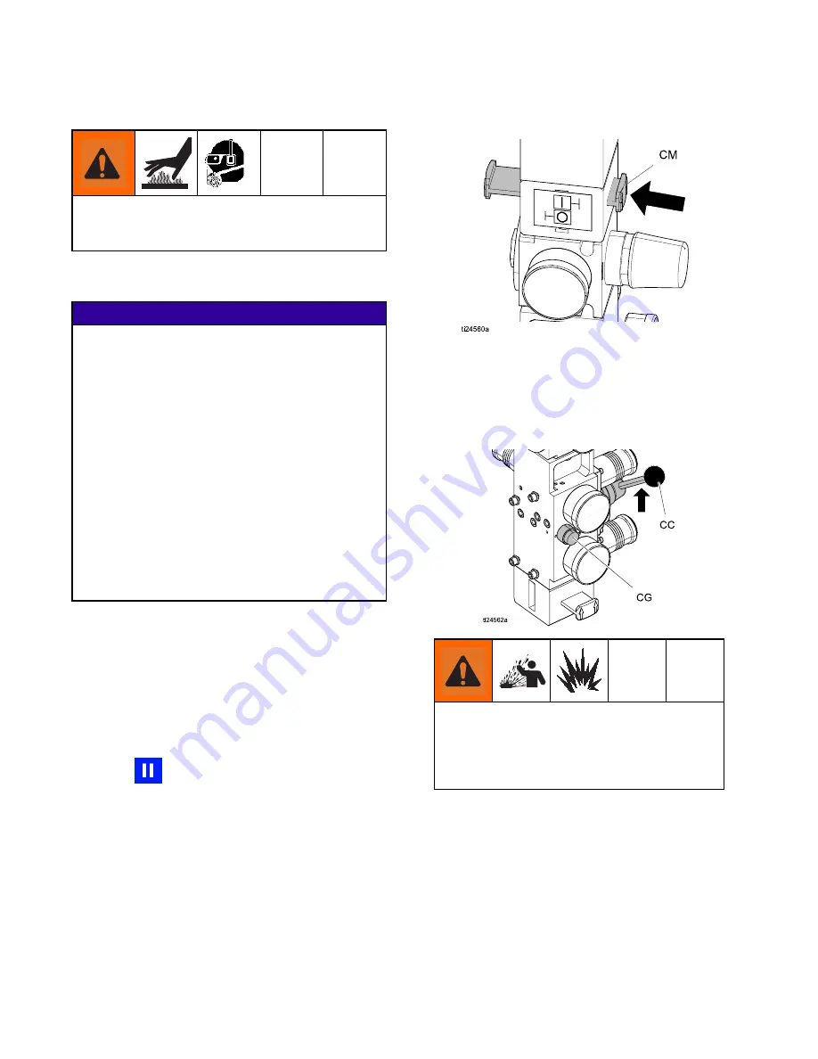
2. Push in the air motor slider valve (CM) to stop
the pump.
3. Set ram director valve (CC) to UP and raise the
platen (G) and immediately press and hold the
blowoff buttons (CG) until the platen is completely
out of the drum. Use minimum amount of air
pressure necessary to push the platen out of the
drum.
Excessive air pressure in the material drum
could cause the drum to rupture, causing
serious injury. The platen must be free to move
out of the drum. Never use drum blowoff air
with a damaged drum.
4. Release the blowoff air button and allow the ram
to rise to its full height.
5. Remove the empty drum.
6. Inspect platen and if necessary, remove any
remaining material or material build-up.
7. Follow steps in
, and
38
334130A
Summary of Contents for 334130A
Page 10: ...Component Identification Electrical Control Enclosure Figure 3 Electrical Enclosure 10 334130A...
Page 57: ...Repair Figure 35 Inside of Electrical Control Enclosure 334130A 57...
Page 65: ...Parts Parts Therm O Flow 200 Supply Unit 334130A 65...
Page 68: ...Parts Electrical Module 68 334130A...
Page 69: ...Parts 334130A 69...


