background image

Instructions - Parts

Level Detection Module 
and Drum Feed Kit

3A2806A

EN

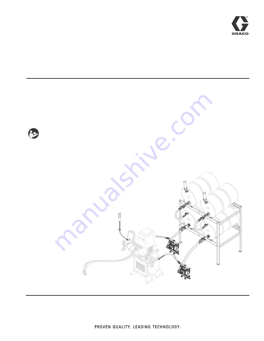
Installation kit to provide low level sensors in both chemical sides of an HFRL 
plural-component proportioner being fed from 55 gallon (208 liter) drums. For professional 
use only. 

Not approved for use in explosive atmospheres or hazardous locations. 

See page 3 for model information.

125 psi (0.86 MPa, 8.6 bar) Maximum Fluid Working Pressure
125 psi (0.86 MPa, 8.6 bar) Maximum Air Input Pressure

Important Safety Instructions

Read all warnings and instructions in the HFRL and HFRS 
Setup-Operations manual. Save all instructions.

ti19596a

Summary of Contents for 24N767

Page 1: ...gallon 208 liter drums For professional use only Not approved for use in explosive atmospheres or hazardous locations See page 3 for model information 125 psi 0 86 MPa 8 6 bar Maximum Fluid Working Pr...

Page 2: ...arrel Style Level Sensors 14 Set the ADM to Recognize the Feed System Kit 14 Set the ADM to Recognize which Level Sensors are to Operate 15 Set the Level Sensors Output Function 15 Startup 16 Shutdown...

Page 3: ...Operated Diaphragm Pump Operation 3A0235 Feed Supply Kits Instructions Parts 406987 GCA CAN Cables Reference Extension Cables Part Description 24N816 KIT low level stack light HFRL Required 2 low lev...

Page 4: ...cation C Level Sensor Empty Indication D Indicator Stack Light E Drum Feed Pump Kit for One Chemical Optional F 4 Drum Rack Optional G Upper to Lower Drum Feed Hose H Drum to Pump Feed Hose 6 ft 1 8 m...

Page 5: ...the inside of the HFRL stand enclosure and includes two fluid control modules Key AA Fluid Control Module FCM A Red Tank AB Fluid Control Module B Blue Tank AC Ground Cable AD CAN Cable AE Flanged Hex...

Page 6: ...h setting indicates which zone the fluid control module will control in the system The FCM uses a 16 position rotary switch to make selections Set the rotary switch to the specific selection according...

Page 7: ...s at the same time as a devi ation or alarm Messaging will be viewable on the ADM to determine the specific error code FIG 5 Component Identification Light Tower Signal Description Green on only Syste...

Page 8: ...uctive metal pails placed on a grounded surface Do not place the pail on a nonconductive sur face such as paper or cardboard which interrupts grounding continuity To maintain grounding continuity when...

Page 9: ...ure components are located properly and will reach the HFRL Refer to FIG 1 page 4 NOTE Drum to pump feed hose length can be reduced if necessary Refer to FIG 1 page 4 item H 4 Tighten all connections...

Page 10: ...e splitter to the panel 7 If there is no available connection on the splitter an alternate CAN connection will need to be used The alternate location may require a different gendered cord 122487 is pr...

Page 11: ...Installation 3A2806A 11 FIG 6 Install Electrical Panel r_24n804 Panel Install Step 5 Step 5 Step 8 Step 9 Step 6 Panel view is shown rotated 180 from the installed position Step 13 Step 6...

Page 12: ...of the well The bottom of the level sensor will be slightly visible through the bottom of the well NOTE In the following step do not allow PTFE paste or tape to cover the tip of the level sensor well...

Page 13: ...oute the light tower cord as needed towards the ADM 4 Connect the cable to the port labeled 1 on the base of the ADM Refer to FIG 1 page 4 NOTE A 5 m 16 ft cable is provided with the level con trol ki...

Page 14: ...be seen through one of the four holes in the sensor well housing c Tighten sensor well nut d Press and hold the button down with the ball end of an allen wrench for two seconds The light will flash sl...

Page 15: ...rom operation when there is a low level condition When a low level is sensed the machine will not cycle until the sensor see material A pop up screen on the ADM alerts the operator of the specific lev...

Page 16: ...ial harden in pump Shutdown See Shutdown in system operation manual Close feed pump bleed type master air valve Pressure Relief Procedure 1 If the optional drum feed kit is being used remove the air p...

Page 17: ...ryer assembly NOTE To prevent contamination of the dessicant in the dryer canister caused by sloshing material it is recom mended that the tape is temporarily placed over the air inlet on the dryer ca...

Page 18: ...Settings USB Logs Recipes Maintenance Counters may be reset to factory default settings Download all settings and user preferences to a USB before the upgrade for ease of restoring them following the...

Page 19: ...Replace FCM Level sensor is sensing material when material is not present Level sensors out of calibration Calibrate level sensor Replace level sensor Level sensors blocked inside reser voir Check ins...

Page 20: ...ottom of the well NOTE In the following step do not allow PTFE paste or tape to cover the tip of the level sensor well If paste comes in contact with the tip of the level sensor well thoroughly wipe i...

Page 21: ...ALE 122487 FEMALE 121002 M12 5 PIN FEMALE HARNESS 122487 OR 121002 CAN COM 1 GND GND CONNECT 121002 TO SPLITTER ON MAIN PANEL OR 122487 TO AVAILABLE CAN PORT ON AN ACCESSORY MODULE FCM1 FCM2 LABEL CAN...

Page 22: ...Parts 22 3A2806A Parts Drum Feed System 24N816 003 004 001 005 005 006...

Page 23: ...ards are available at no cost Ref Part Description Quantity 001 24N804 PANEL assy fluid control HFRL Inside Enclosure Refer to FIG 2 page 5 1 003 255468 KIT acc light tower TC ram 1 004 124003 CABLE C...

Page 24: ...24 3A2806A Drum Feed Kit 24N767 100 116 117 118 119 118 115 127 123 127 115 114 129 110 121 130 120 126 125 107 101 128 124 106 104 102 103 102 105 130 108 122 125 109 108 111 112 106 128 124 r_24n767...

Page 25: ...apter 1 110 94 0758 99 FITTING npl hex 1 x3 4npt mm ms 2k 1 111 94 0433 99 FITTING nipple hex 1npt mm 4 5k 1 112 123250 FITTING coupling 1 5nptx1npt cs 1 114 123890 FITTING tee 1nptx1nptx1nptf fff c 1...

Page 26: ...Parts 26 3A2806A Electric Panel 24N804 r_24n804_parts1 206 205 204 203 211 212 215 212 204 212 211 210 202 201 224 213 214 219 220 208 208 220 207 233 204 215 234 209 209 215 or 225...

Page 27: ...Parts 3A2806A 27 r_24n804_parts2 217 213 214 218 220 223 221 222 225 224 216...

Page 28: ...3452 HOLDER anchor wire tie nylon 3 214 116610 SCREW mach phil pan 10 3 215 24H240 HARNESS wire ground term 9 1 216 100020 WASHER lock 1 217 100166 NUT full hex 1 218 123679 BUSHING wire protector 1 3...

Page 29: ...Parts 3A2806A 29...

Page 30: ...m C Width 60 1 2 in 154 cm Anchor Locations D Width 57 1 2 in 146 cm E Length 33 1 2 in 85 cm F Diameter 0 56 in 1 4 cm 305 304 302 301 305 305 305 305 01_0955_25 NOTICE To avoid machine damage or per...

Page 31: ...ntity 301 01 0955 A 99 SHELF rack 4 drum 2 302 01 0955 B 99 SUPPORT shelf rack 2 4 drum right 1 303 01 0955 C 99 SUPPORT shelf rack 2 4 drum left 1 304 01 0955 D 99 STRAP stabilizer rack 4 drum 2 305...

Page 32: ...sensor in each drum feed configure as shown below Activate mid and low sensors and set refill setting to monitor Advanced Screen 1 This screen allows the user to set the language date format current...

Page 33: ...Check this box to enable cavitation alarms in Operator Mode Clear this box to disable cavitation alarms in Operator Mode Complete Dispense with Setpoint Error When this box is checked the shot will co...

Page 34: ...p Screens Overview 34 3A2806A Advanced Screen 5 This screen displays software information If the level controls are present but not active the tank monitor program will not appear in the advanced 5 sc...

Page 35: ...is sensed the pop up error code appears and the active error display reads Red Low Material Level The light stack will flash yel low and the audible alarm will sound When this error occurs the machine...

Page 36: ...o dispense when a start is initiated unless the Low Material Disables Dis pense flag is set Refer to Advanced Screen 3 to configure the machine to stop dispensing when a low level sensor is triggered...

Page 37: ...Maximum sound power Inlet Outlet Sizes Air inlet size 1 2 NPTF Materials of Construction Wetted materials Carbon steel PTFE Stainless Steel PE Aluminum Nylon Weight 24N816 16 lb 7 3 kg 24N767 Optional...

Page 38: ...ipment does not disclose any defect in material or workmanship repairs will be made at a reasonable charge which charges may include the costs of parts labor and transportation THIS WARRANTY IS EXCLUS...

Reviews: