Setup Procedure
Warning:
Do not exceed the maximum air pressure to the reservoir extend side of the ram, or the
maximum air pressure on the retract side of the ram. See page 2 for maximum pressure rating.
Warning:
Do not the material outlet pressure. See page 2 for maximum pressure rating.
Caution:
Raise the slide valve towards the regulator; this will release the air pressure from the extend
side of the ram.
Note:
It is not necessary to turn the air supply off at the air source, or disconnect the air supply line to the
regulator.
Mount the cartridge retainer using the bracket and clamp provided to either a 1/2 in. horizontal or vertical
rod. The cartridge retainer is designed to be vertical; however it may sometimes be positioned at other
angles -- consider the material, material packaging, and access/service to the cartridge before doing this.
Move the slide valve towards the regulator
(up typical)
.
This relieves air pressure from the extend side of
the ram, and relieves material outlet pressure.
Connect the material pressure air supply (from controller or from air source) to the pressure regulator.
Apply retract air pressure to the retract air port of the ram, this will send the ram into the up position
releasing pressure on the cartridge retainer. Loosen the four retaining knobs and swing them down and
away from the reservoir cap. Slide the retainer ring and the retainer down, away from the reservoir cap.
Insert the red outlet fitting to the material cartridge;
do not apply PTFE tape or pipe sealant and hand
tighten only
. Insert the 1/4-inch female FNPT hose fitting to the red outlet fitting. Insert the cartridge into
the retainer. Slide the retainer and the retainer ring back up to the reservoir cap. Align the slots in the
reservoir cap with the hold-down links. Move the four retaining knobs up to their retaining position. Tighten
these retaining knobs securely. Attach the material hose to the 1/4-inch female FNPT fitting on the red
outlet fitting on the bottom of the cartridge. Connect the material hose from the cartridge to the dispense
valve. Remove air pressure from the retract side of the ram. Move the slide valve away from the regulator
(down typical) to pressurize the extend ram. Apply air pressure to the extend side of the ram; increase the
pressure to 20 psi (1.3 bar) to start. Adjust the flow control valve to give a slow smooth retract stroke.
Check all air fittings and the retainer for leaks. Increase air pressure to purge the dispense valve of air and
until the desired flow rate is achieved.
The cartridge retainer is ready to be placed in service.
You must adjust the pressure to the extend ram according to the type of material being dispensed. Too
low a pressure will give an inconsistent dispensed volume because the dispense valve does not fill
completely during cycling. Too high a pressure may cause material separation or packing. Use the
minimum pressure needed to get smooth material flow during the purge cycle.
3
Summary of Contents for 24H683
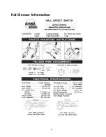
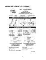
Page 14: ...Hall Sensor Information 14 ...


