background image

Instructions – Parts List

GRACO INC.P.O. BOX 1441MINNEAPOLIS, MN55440-1441

Copyright 1995, Graco Inc. is registered to I.S. EN ISO 9001
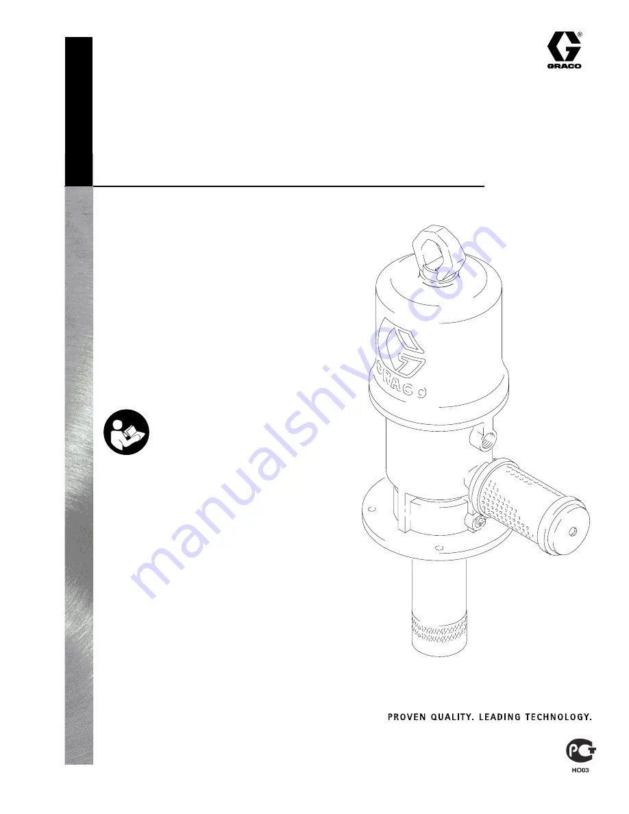
6:1 Fire–Ball

r

425 Pump

For pumping non–corrosive and 
non–abrasive oils and lubricants only.

Model 238108, Series D

1100 psi (7.6MPa, 76 bar) Maximum Working Pressure

180 psi (1.2 MPa, 12 bar) Maximum Air Input Pressure

308608K

06031

Important Safety instructions

Read all warnings and instructions in this manual.
Save these instructions.

Summary of Contents for 238108

Page 1: ...1 6 1 Fire Ballr 425 Pump For pumping non corrosive and non abrasive oils and lubricants only Model 238108 Series D 1100 psi 7 6MPa 76 bar Maximum Working Pressure 180 psi 1 2 MPa 12 bar Maximum Air Input Pressure 308608K 06031 Important Safety instructions Read all warnings and instructions in this manual Save these instructions ...

Page 2: ...r Graco distributor D Do not alter or modify this equipment D Check equipment daily Repair or replace worn or damaged parts immediately D Do not exceed the maximum working pressure stated on the equipment or in the Technical Data for your equipment Do not exceed the maximum working pressure of the lowest rated compo nent in your system D Use fluids and solvents which are compatible with the equipm...

Page 3: ... your body and cause extremely serious injury including the need for amputation Fluid splashed in the eyes or on the skin can also cause serious injury D Fluid injected into the skin may look like just a cut but it is a serious injury Get immediate surgical treatment D Do not point the dispensing valve at anyone or at any part of the body D Do not put your hand or fingers over the end of the dispe...

Page 4: ...r ventilation open flames or sparks can cause a hazardous condition and result in a fire or explosion and serious injury D Ground the equipment Refer to Grounding on page 7 D If there is any static sparking or you feel an electric shock while using this equipment stop dispensing immediately Do not use the equipment until you identify and correct the problem D Provide fresh air ventilation to avoid...

Page 5: ...ed type master air valve required B Air line filter C Air regulator and gauge D Pump runaway valve shown for position not needed if you use a low level cut off valve E Air inlet F Ball valve for releasing collected moisture G Pump H Drain valve required J Dispensing valve model 222411 shown K Thermal relief kit required Part No 240429 L Male quick disconnect fitting M Female quick disconnect coupl...

Page 6: ... be sufficient The thermal relief kit assists in relieving pressure in the pump hose and dispensing valve due to heat expansion The ground wire reduces the risk of static sparking WARNING 1 Screw the muffler 5 into the 3 4 in npt muffler port and tighten it using a wrench on the flats of the muffler near the male threads 2 Install an air line lubricator N for automatic air motor lubrication 3 Inst...

Page 7: ...3 Air compressor Follow manufacturer s recom mendations 4 Fluid supply container Follow the local code 5 To maintain grounding continuity when flushing or relieving pressure always hold a metal part of the valve firmly to the side of a grounded metal pail then trigger the valve To ground the pump remove the ground screw Z and insert through the eye of the ring terminal at end of the ground wire Y ...

Page 8: ...put Limit the air to the pump so that no air line or fluid line component or accessory is overpressurized WARNING WARNING HAZARDOUS VAPORS The air motor exhaust coming out of the muffler could contain harmful materials such as oil antifreeze or some of the material being pumped 1 With the air regulator C closed open the bleed type master air valves A or if so equipped join the quick disconnect cou...

Page 9: ...sassembling the pump Problem Cause Solution Pump fails to operate Inadequate air supply pressure or restricted air lines Increase air supply clear Closed or clogged dispensing valve Open clear Clogged fluid lines hoses valves etc Clear Damaged air motor Service air motor Exhausted fluid supply Refill and reprime or flush Continuous air exhaust Worn or damaged air motor gas ket packing seal etc Ser...

Page 10: ...4 Use a strap wrench on the displacement pump cylinder 110 to screw it out of the air motor base 28 See Fig 3 5 Remove the piston valve seat 109 from the rod 29 with wrenches or with the vice and a wrench 6 Remove the piston ball 103 u cup packing 107 and piston washer 113 7 Remove the air motor base from the vice and place the piston rod 29 flats in the vice with the air motor up 8 Loosen the lif...

Page 11: ...ith your other hand so as to catch the spring loaded toggle assemblies when they snap out of the lugs Place the tip of a screwdriver into the piston between the piston lugs L below the pivot pins 16 on the toggles pry up with the screw driver handle to compress the springs on the toggle assembly M up and away from the piston lugs and remove the parts See Fig 4 16 Straighten the lockwires 22 and re...

Page 12: ...17 5 Thread the top valve nuts 21 onto the inlet valve poppets 32 until one thread of the inlet valve poppets is exposed above the valve nuts 6 Install the toggle pins 15 in the yoke 13 place the toggle arm 23 ends of the toggle assembly M onto the toggle pins and snap the pivot pin 16 ends of the toggle assembly into the lugs L 7 Measuring with the gauge Part No 171818 create 0 125 in 3 18 mm of ...

Page 13: ...l the u cup packing 107 with the lips up and place the piston washer 113 on the piston valve seat 109 Make sure the lips of the u cup packing face up See Fig 3 17 Place the piston ball 103 in the piston rod 29 18 Clean the threads of the piston valve seat Apply Loctiter to the threads 109 and thread the assembly from Step 16 onto the piston rod 29 19 Clamp the flats of the piston valve seat 109 in...

Page 14: ... 2 Unscrew the valve housing 111 Remove the o ring 105 retainer 112 and ball 104 3 Inspect the parts for wear or damage If the ball is nicked replace it Reassemble using grease on the male threads Displacement Pump See Fig 5 NOTE Clean and inspect all parts for wear or damage as you disassemble them Replace parts as needed For best results always replace all the o rings and packings when you disas...

Page 15: ...re See pages 16 and 17 Ref No Part No Description Qty 10 113345 SEAL u cup shown on page 16 1 103 101190 BALL piston metallic 1 104 101178 BALL sst 1 105 113347 PACKING o ring 1 107 113346 PACKING u cup 1 108 112349 PACKING o ring 1 Ref No Part No Description Qty 109 194016 PISTON 1 110 190922 CYLINDER pump 1 111 190926 VALVE HOUSING 1 112 190928 RETAINER ball 1 113 190924 WASHER piston 1 Included...

Page 16: ...s Drawing 16 24 11 30 22 21 25 23 12 21 17 26 19 27b 27a 31 15 13 27c 32 29 3 10 7 18 2 See Displacement Pump Parts Drawing and List on page 15 36 1 2 1 Lips must face down Torque to 30 to 40 ft lb 41 to 54 N m 06032 20 5 28 27 ...

Page 17: ... 190929 RING lift 1 25 167585 SPRING helical compression 2 26 170709 POPPET exhaust valve 2 27 207391 PISTON includes items 27a to 27c also includes 207385 repair kit when ordered as a replacement part 1 27a 102975 SCREW rd hd mach 6 32 x 1 4 2 27b 158361 CLIP Spring 2 27c BARE PISTON not sold separately 1 28 190927 BASE air motor 1 29 193799 ROD piston 1 30 15E954 CYLINDER air motor 1 31 207150 R...

Page 18: ...luid pressure ratio 6 1 Air operating range 40 to 180 psi 3 to 12 bar 0 3 to 1 2 MPa Air consumption 7 ft3 min per gallon pumped 0 051 m3 min per liter pumped at 100 psi 7 bar 0 7 MPa Pump cycles per gallon liter 14 5 3 8 Maximum recommended pump speed 78 cycles min 6 gpm 23 liter min Recommended speed for optimum pump life 15 to 25 cycles per min Piston seals polyurethane with nitrile spreader Ro...

Page 19: ...ar inlet air pressure D 40 psi 2 8 bar inlet air pressure 55 2 48 3 41 4 34 5 27 6 20 7 13 8 6 90 To find Pump Air Consumption scfm or m3 min at a specific fluid flow gpm lpm and operating air pressure bar psi 1 Locate desired fluid flow along bottom of chart 2 Follow vertical line up to point of intersection with selected air consumption curve 2 Align point on curve with vertical scale on left si...

Page 20: ... above The buyer agrees that no other remedy including but not limited to incidental or consequential damages for lost profits lost sales injury to person or property or any other incidental or consequential loss shall be available Any action for breach of warranty must be brought within two 2 years of the date of sale Graco makes no warranty and disclaims all implied warranties of merchantability...

Reviews: