All Rights reserved, No Spreading without GOSUNCN Permission
34
Hardware Development Guide
ME3616
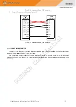
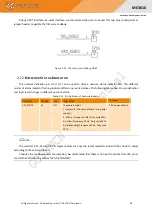
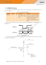
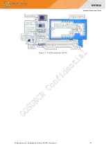
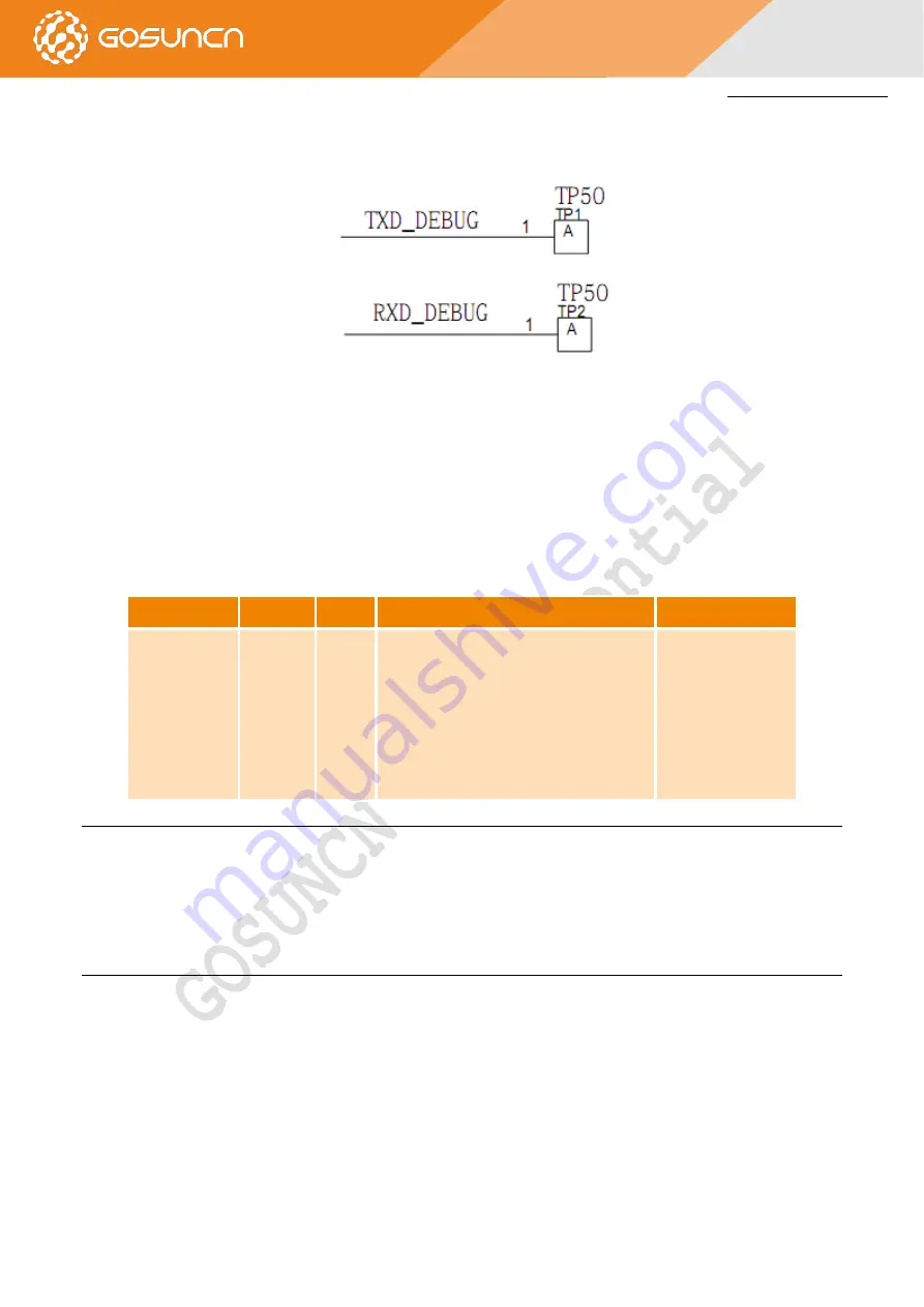
Debug UART Interface is 2-wires interface, we recommend the user to connect this two pins to test points or
jumper header to update the firmware or debug.
Figure 2-25 The test point of debug UART
2.12.
N
ETWORK
S
TATUS
I
NDICATOR
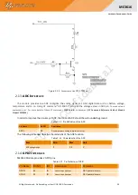
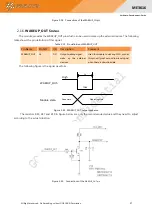
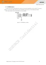
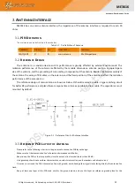
The network indication pin
SYS_STATE
can be used to drive a network status indicator LED. The different
modes of status indicator flashing indicate different network statuses. The following tables describe pin definition
and logic level changes in different network status.
Table 2-14 Pin Definition of Network Indicator
Pin Name
Pin NO.
I/O
Description
Comment
SYS_STATE
21
DO
There are 4 status:
1. power off(the same as there is no power
supply)
2. offline(Frequency 1Hz,Duty cycle 50%)
3. online(Frequency 0.3Hz,Duty cycle 10%)
4. data sending(Frequency 10Hz,Duty cycle
50%)
1.8V power domain
NOTE:
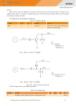
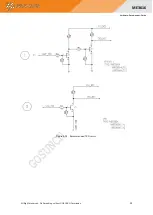
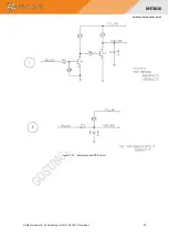
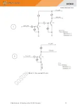
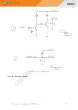
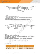
The resistors R11, R12 and R7 in Figures below are only the recommended value and they need to adjust
according to the actual situation.
Consider the sensitive power consumption, we recommend that there is no need to connect this LED pin or
control the LED status by command “AT+ZCONTLED”

