26
GMC-I Messtechnik GmbH
8.2.
Communication Modules
(no longer available)
8.2.1.
Applicable to All Modules
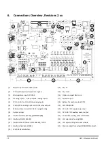
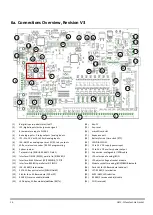
The SMARTCONTROL’s communication interface can be adapted to your requirements via the socket slot (DIL64)
[see item 25 in section 6. , “Connections Overview,”]. These are optional and are not included with the
SMARTCONTROL. The following options are available: analog modem, ISDN, GSM/GPRS and Bluetooth.
Note:
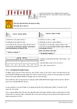
Before beginning any work, disconnect the entire system from all sources of electrical power
Never insert a socket module when the system is switched on [refer to section 9.3. , “Shutting
Down and Restarting SMARTCONTROL”].
Electrostatic charging must be avoided.
Provide for electrostatic discharging of personnel and tools before beginning work.
Before inserting the module, make sure that the correct operating voltage has been selected for
the respective module.
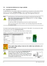
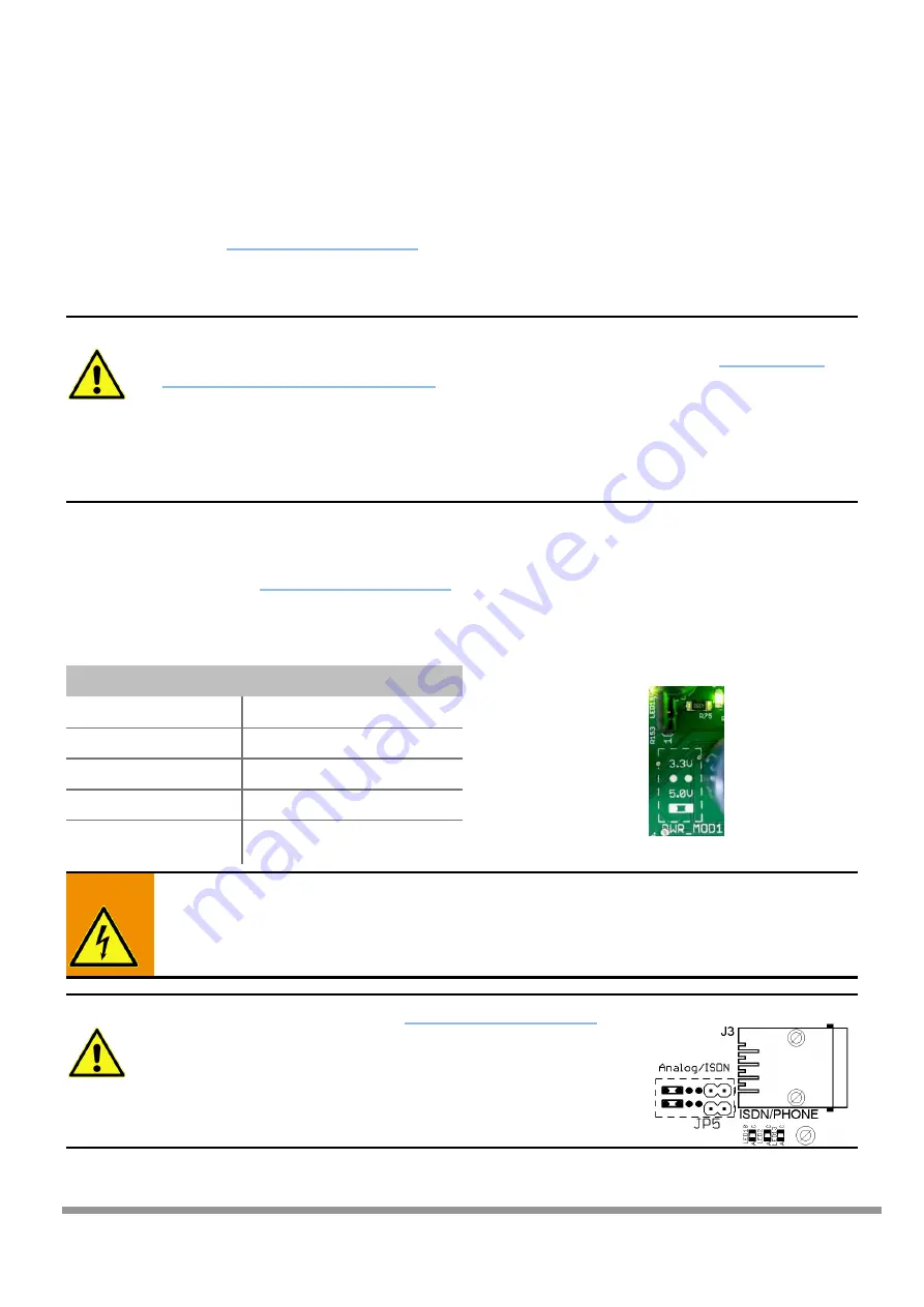
The module’s operating voltage is determined by jumper series JP3, “PWR_MOD1”, at the left above the modem
slot [see item 25 in section 6. , “Connections Overview,”].
The default setting is 3.3 V for operation with analog modems and ISDN modules.
Otherwise, insert jumper JP3 such that the required operating voltage is selected.
Warning:
If the supply voltage setting is incorrect, the module may malfunction, or it
may be damaged.
Note:
Jumper JP5 [see item 23 in section 6. , “Connections Overview,”] is
used to configure the ISDN/PHONE-RJ45 connector jack to
analog/ISDN operation. Make sure that the jumper configuration is
correct before initial start-up. A jumper must be plugged onto both
JP5 pins identified analog/ISDN. The jumpers have to be removed
for GSM/GPRS or Bluetooth modules.
Module Type
Voltage to be Selected
Analog modem
3.3 V
ISDN
3.3 V
Bluetooth
3.3 V
GSM, 3.3 V version
3.3 V
GSM, 5 V version
5.0 V
PWR_MOD1/
Jumper JP3

