20
GMC-I Messtechnik GmbH
6
Measurements
6.1
Enabling Parameter Changes
A password must be entered in order to adjust the parameters for
each of the following measurements:
•
RISO: change test voltage
•
m
/4: change test current
Entering the Password for Changing Parameters
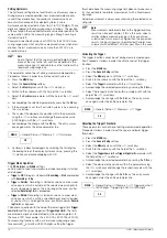
As soon as you attempt to change, for example, test voltage U
set
via the
scroll keys, the “Password” menu appears. Enter the
current password as described in chapter 4.4.6.
Note
If you’ve forgotten your password, please contact our
product support department (see phone number in chap-
ter 1.1).
Changing the Password
A previously selected password can be changed in the “General
Setup” menu (see chapter 4.4.6).
6.2
Insulation Resistance Measurement – RISO Function
6.2.1
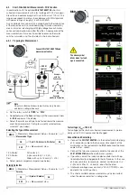
Preparing for Measurement
Note
Checking the Measurement Cables
The test probes at the ends of the measurement cables
should be short circuited before performing insulation
resistance measurements with the selector switch in the
position, in order to make sure that a value close to 0
is displayed at the instrument. In this way, incorrect con-
nection can be avoided and broken measurement cables
can be detected.
Note
Insulation resistance may only be measured at voltage-
free devices.
The measurement cables may not come into contact with
one another during high-resistance insulation measure-
ments.
➭
Set the rotary switch to “
RISO
” or “
COIL
”.
➭
Connect the measurement cables to the accessible M
and
sockets, using the included probe for connection to the M
socket if possible.
➭
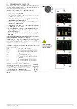
Interference voltage measurement (V AC+DC TRMS) is con-
ducted in this switch position.
The
START
key may only be pressed when the device under test is
voltage-free (display:
Uext
< 10 V).
Note
The “
RISO
” or “
COIL
” switch position may only be used for
insulation resistance measurement and short-circuited
coil detection. However, if interference voltage is inadver-
tently applied with the switch in this position, it appears at
the display. If an interference voltage of
Uext
15 V AC or
> 25 V DC is present within the system, insulation resis-
tance measurement is disabled. The display panel con-
tinues to show the interference voltage value. If a voltage
of greater than 1000 V is present, an acoustic signal is
generated as well.
S–
A
V
Temp
m
/4
COIL
S+
00.00
Short circuit the measurement cables.
R
x
0 V!
!
Temp
Interference Voltage Detection
RISO
COIL


