GMC-I Gossen-Metrawatt GmbH
57
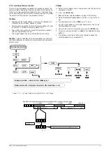
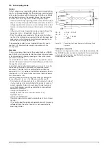
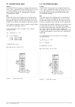
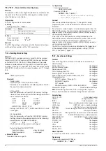
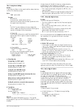
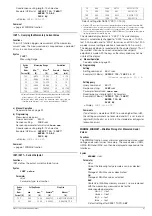
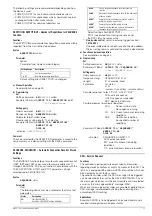
5.10 Varying the Internal Output Resistance Value
Functions
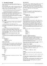
In the voltage regulating mode, internal output resistance has a
value of close to 0
Ω
.
The internal output resistance value can be increased for certain
applications, for example simulation of long output cables or
weak automotive batteries. The selected (open-circuit) output
voltage is reduced in proportion to increasing load (Figure 5.10a).
Figure 5.10a
Output Voltage Relative to Load
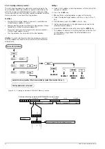
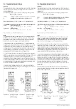
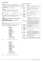
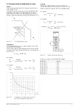
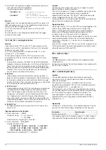
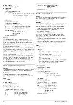
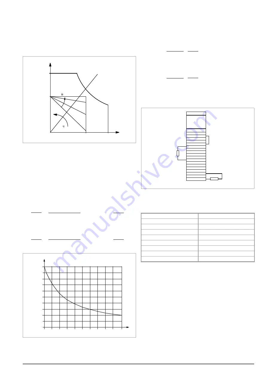
Standardization
The standard characteristic curve shown in Figure 5.10b is valid
for all KONSTANTER models.
Quick and easy determination indicating which output resistance
R
i
correlates to any given control resistance R
ext
is made possible
with the curve.
R
i
= R
imax
⋅
display value
80 V models:
52 V models:
Figure 5.10b
Standardized Curve for Determining Internal Output
Resistance for a Specified Control Resistance
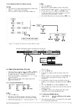
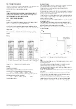
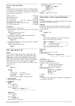
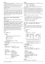
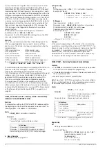
Connection
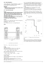
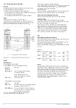
Connect the analog interface as shown in Figure 5.10c.
The following relationship between internal resistance R
i
and
control resistance R
ext
applies with this wiring configuration:
80 V models:
52 V models:
Example:
U
nom
= 80 V, I
nom
= 25 A, R
i
is 0.5
Ω
===> R
ext
= 186.108 k
Ω
Figure 5.10c
Wiring for Varying Internal Resistance
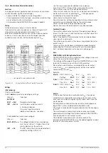
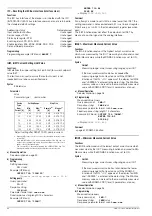
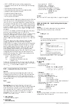
Table of R
imax
Values for All KONSTANTER Models
Unom
Inom
U/V
I / A
Iset
Uset
0
R
L
R
L
↑
R
i
m
ax
R
ext
=
0
R
i
min
≅
R
ext
= ∞
R
ext
↑
R
imax
= 1.281
⋅
U
nom
I
nom
R
imax
25.68 k
Ω
R
ext
+25.68 k
Ω
R
i
=
;
R
imax
= 1.251
⋅
U
nom
I
nom
R
imax
24.82 k
Ω
R
ext
+24.82 k
Ω
R
i
=
;
R
i
/ R
imax
0.8
0.6
0.4
0.2
R
ext
0
20
40
60
80
100
[k
Ω
]
1
Device Type
R
imax
(
Ω
)
62 N 52 RU 25 P
2.602
62 N 52 RU 50 P
1.301
64 N 52 RU 100 P
0.651
64 N 52 RU 150 P
0.434
62 N 80 RU 12.5 P
8.198
62 N 80 RU 25 P
4.099
64 N 80 RU 50 P
2.05
64 N 80 RU 75 P
1.366
U
nom
I
nom
33.12 k
Ω
R
i
R
ext
=
⋅
– 25.86 k
Ω
U
nom
I
nom
31.04 k
Ω
R
i
R
ext
=
⋅
– 24.82 k
Ω
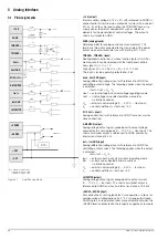
Analog Interface
+15 V
AGND
T
TRIGGER
−
Uset +
Uset GND
M/S Uset +
Settings:
Load
SSP KONSTANTER
−
SENSE
+SENSE
U-MONITOR
Iset +
Iset GND
+OUT
I-MONITOR
–OUT
R
ext