


3B3-6 POWER STEERING
— Sealing and bearing surfaces of the pitman
shaft (
221
) for roughness, nicks, or other dam
age. Replace the pitman shaft assembly if nec
essary.
— Pitman shaft (221) for excessive wear or scor
ing. C heck the se ctor gear teeth fo r w ear.
Replace the pitman shaft assembly if neces
sary.
— Adjuster screw (222) threads for wear. The
adjuster screw must be free to turn with no end
play.
2. Rack piston.
— Worm (248) and rack piston (214) grooves and
all balls (213) for scoring. BOTH M UST BE
REPLACED as a matched assembly.
— Seal (216) and ring (217) for wear.
— Ball return guide halves (212) for cracks and
damaged.
— Bearing (247) and races (246) for scoring and
excessive wear.
— Rack piston (214) teeth and external ground
surfaces for scoring or excessive wear. If either
condition exists, replace the rack piston (214)
and worm (248).
3. Adjuster plug.
— Spacer (235) for wear or cracks.
— Races (236, 238) for wear or scoring.
— Adjuster plug (240) threads for wear.
— Bearing (237) for wear or scoring.
— Needle bearing (241) for wear, pitting or scor
ing. Replace if necessary.
4. Valve and stub shaft.
— Seals (231) and rings (232).
— Shaft pin for wear or cracks. If excessively worn
or broken, replace the com plete valve and shaft
assembly.
— Ground surface of the stub shaft (251). If a cro
cus cloth ca nn ot clean the nicks or burrs,
replace the entire valve assembly.
— Outside diam eter of the valve spool and inside
diam eter of the valve body (250). If a crocus
cloth cannot clean the nicks or burrs, replace
the entire shaft and valve assembly.
— The small notch in the skirt of the valve for wear.
If worn replace the com plete valve assembly.
— Valve spool inside the valve body (250). The
valve spool, when lubricated with steering fluid,
must rotate freely w ithout binding. If binding
occurs, replace the com plete valve and shaft
assembly.
ASSEMBLY
■►4* install or Connect (Figures 1 ,4 , and 10 through 14)
Tools Required
J 4245 Snap Ring Pliers
J 6217 Valve C onnector
J 21552 Ball Retainer
J 22407 Bearing Installer
J 8092 Bearing Driver
J 7079 Bearing Remover and Installer
J 8524-1 Driver
J 7624 Bearing Preload Spanner W rench
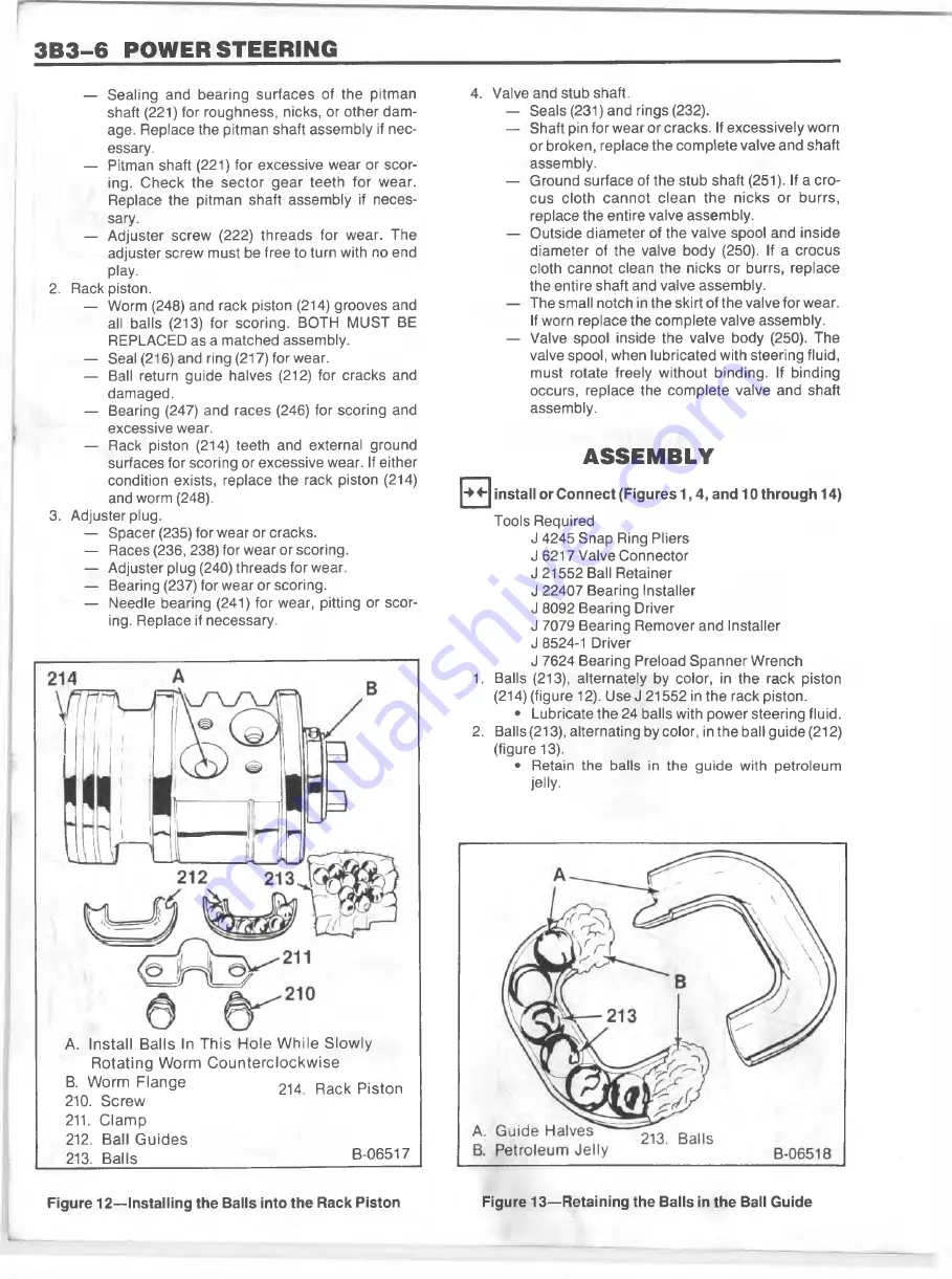
1
. Balls (213), alternately by color, in the rack piston
(214) (figure
1
2). Use J 21552 in the rack piston.
• Lubricate the 24 balls with power steering fluid.
2. Balls (213), alternating by color, in the ball guide (212)
(figure 13).
• Retain the balls in the guide with petroleum
jelly.
A. In s ta ll B a lls In T h is H o le W h ile S lo w ly
R o ta tin g W o rm C o u n te rc lo c k w is e
B. W orm F la n g e
2 U
R ack p js to n
210. S cre w
211. C la m p
212. Ball G u id e s
213. B a lls
B-06517
F ig u re 1 2 — Installing th e Balls into th e R ack P iston
Figure 1 3 — R etain in g th e B alls in th e Ball G uide
Summary of Contents for 1989 Light Duty Truck
Page 1: ...vr V Light Duty Truck Unit Repair Manual...
Page 2: ......
Page 11: ...GENERAL INFORMATION OA 5 Figure 8 RV Models...
Page 13: ...GENERAL INFORMATION OA 7 Figure 11 ST Models...
Page 18: ......
Page 44: ......
Page 76: ...1B3 18 R 4 AIR CONDITIONING COMPRESSOR N...
Page 114: ......
Page 162: ......
Page 176: ...4B3 14 91 2 INCH RING GEAR...
Page 192: ...4B5 4 DANA REAR AXLES Figure 4 Spreading the Differential Case Figure 7 Removing the Ring Gear...
Page 218: ......
Page 220: ...4B6 2 12 INCH RING GEAR ROCKWELL F 04734 Figure 1 Rear Axle Components...
Page 229: ...12 INCH RING GEAR ROCKWELL 4B6 11 SPECIAL TOOLS Special Tools...
Page 230: ...4B6 12 12 INCH RING...
Page 240: ...4B7 10 LOCKING DIFFERENTIALS SPECIAL TOOLS Special Tools...
Page 260: ...4C2 6 93 4 INCH RING GEAR FRONT AXLE Figure 16 Removing the Pinion Inner Bearing...
Page 273: ...T TRUCK FRONT AXLE 4C3 3 F 05785 Figure 1 Axle Components...
Page 291: ...K TRUCK FRONT AXLE 4C4 3 Figure 1 Front Axle Com ponents K 15 25 Models...
Page 293: ...K TRUCK FRONT AXLE 4C4 5 Figure 3 Front Axle Com ponents K35 Models...
Page 318: ...C4 30 K TRUCK FBOHT AXLE...
Page 334: ......
Page 361: ...2 5 LITER L4 ENGINE 6A1 5 Figure 3 Cylinder Head Manifolds and Components...
Page 363: ...2 5 LITER L4 ENGINE 6A1 7 F 05715 Figure 5 Block and Components...
Page 395: ...2 8 LITER V 6 6A2 3 Figure 1 Engine Lubrication Diagram...
Page 396: ...6A2 4 2 8 LITER V 6 Figure 2 Engine Lubrication Diagram...
Page 424: ...6A2 32 2 8 LITER V 6...
Page 427: ...I 4 3 LITER V 6 6A3 3 Figure 1 Engine Lubrication Diagram B 07857...
Page 451: ...4 3 LITER V 6 6A3 27 SPECIFICATIONS ENGINE SPECIFICATIONS F 6344...
Page 457: ...4 8 LITER L6 6A4 3 Figure 2 Lubrication Diagram Front View...
Page 460: ...6A4 6 4 8 LITER L6 C 1 107 112 fK 108 3 109 165 129 B 05056 Figure 5 Block and Components...
Page 490: ...Ml...
Page 493: ...V8 ENGINE 6A5 3 Figure 1 Lubrication Diagram 5 0L and 5 7L Engines...
Page 494: ...6A5 4 V8 ENGINE Figure 2 Lubrication Diagram 5 0L and 5 7L Engines...
Page 530: ...6A5 40 V8 ENGINE Figure 81 Exhaust Manifold 7 4L Engines Figure 82 Water Pumps and Components...
Page 571: ...6 2 LITER DIESEL 6A7 35 Figure 58 Vacuum Pump Installed...
Page 576: ......
Page 582: ...6C1 6 MODEL 1MEF CARBURETOR Figure 9 Monojet Model 1MEF...
Page 604: ...6C2 6 MODEL M4MEF CARBURETOR Figure 9 Model M4MEF...
Page 640: ...6C4 8 MODEL 700 THROTTLE BODY...
Page 652: ...nmm...
Page 672: ......
Page 693: ...DISTRIBUTORS 6D5 13 Figure 27 Testing the Pickup Coil Figure 28 Testing the Ignition Coil...
Page 696: ......
Page 698: ...7A1 2 700 R4 AUTOMATIC TRANSMISSION Figure 1 Case and External Parts J H 0 0 5 3 7 0 0 R 4 R 2...
Page 745: ...700 R4 AUTOMATIC TRANSMISSION 7A1 49...
Page 762: ...7A2 2 400 475 AUTOMATIC TRANSMISSION Figure 1 Case and External Parts H H 0021 400 R 3...
Page 773: ...400 475 AUTOMATIC TRANSMISSION 7A2 13 Figure 29 Internal Parts H H 0 0 4 3 4 0 0 R 2...
Page 797: ...400 475 AUTOMATIC TRANSMISSION 7A2 37 Figure 93 Control Valve Assem bly...
Page 803: ...400 475 AUTOMATIC TRANSMISSION 7A2 43 Figure 104 Bushing Replacement Procedure...
Page 808: ...J c I i sal...
Page 838: ......
Page 840: ......
Page 842: ......
Page 850: ...7B1 12 HM 290 MANUAL TRANSMISSION J i t i a x V L...
Page 856: ...7B1 18 HM 290 MANUAL TRANSMISSION...
Page 892: ...7B1 54 HM 290 MANUAL TRANSMISSION Figure 93 Special Tools...
Page 897: ...HM 117 TRANSMISSION 7B2 5...
Page 901: ...HM 117 TRANSMISSION 7B2 9 B 05180 Figure 17 Installing the 1st and 2nd Synchronizer...
Page 912: ...20 HM...
Page 924: ...7B3 12 NEW PROCESS TRANSMISSION SPECIAL TOOLS...
Page 927: ...BORG WARNER TRANSMISSIONS 7B4 3 Figure 2 77 mm Transmission and Components...
Page 940: ...i ii iii m i in m i...
Page 944: ...7D1 4 TRANSFER CASE FO 5688 Figure 3 NP205 Transfer Case...
Page 952: ...7D1 12 TRANSFER CASE...
Page 963: ...NEW PROCESS 241 TRANSFER CASE 7D2 11 Figure 17 Oil Pump Pickup Screen Doweled Case Holes...
Page 964: ...7D2 12 NEW PROCESS 241 TRANSFER CASE Figure 18 NP 241 Transfer Case Cut Away...
Page 978: ......
Page 981: ...BORG WARNER 1370 TRANSFER CASE 7D4 3 J...
Page 992: ...7D4 14 BORG WARNER 1370 TRANSFER CASE Figure 26 Installing the Rear Output Yoke...
Page 993: ...BORG WARNER 1370 TRANSFER CASE 7D4 15 Figure 27 BW 1370 Transfer Case...
Page 997: ......
Page 998: ...X 8937...