


0020239562_04 EASICOM 3 Installation and maintenance instructions
37
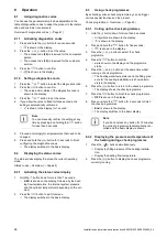
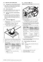
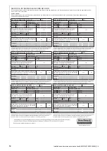
13.6.6 Replacing the expansion vessel
1.
Drain the product. (
B
C
1
2
3
A
D
2.
Undo the nut
(3)
.
3.
Remove both screws on the support plate
(1)
.
4.
Remove the support plate .
5.
Pull out the expansion vessel
(2)
towards the front.
6.
Insert a new expansion vessel into the product.
7.
Screw the new expansion vessel onto the water con-
nection. To do this, use a new seal.
8.
Attach the support plate using both screws.
9.
Fill and purge the product and, if necessary, the heating
installation.
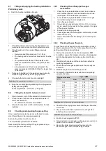
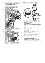
13.6.7 Replacing the PCB
C
C
D
B
A
A
1.
Open the electronics box.
2.
Pull all of the plugs out from the PCB.
3.
Undo the clips on the PCB.
4.
Remove the PCB.
5.
Install the new PCB in such a way that it clicks into the
groove at the bottom and into the clip at the top.
6.
Plug in the PCB plugs.
7.
Close the electronics box.
13.6.8 Replacing the PCB for the user interface
B
C
C
D
A
A
1.
Open the electronics box.
2.
Pull the plug out of the PCB.
3.
Undo the clips on the PCB.
4.
Remove the PCB.
5.
Install the new PCB in such a way that it clicks into the
groove at the bottom and into the clip at the top.
6.
Plug in the PCB plug.
7.
Close the electronics box.
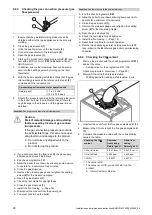
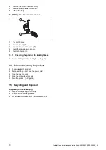
13.6.9 Replacing the expansion relief valve
1
2
1.
Remove the clip
(2)
.
2.
Remove the expansion relief valve.
3.
Fit the new expansion relief valve with a new O-ring.
4.
Reattach the clip
(2)
.
13.6.10 Replacing the volume flow sensor
1
B
A
1.
Pull out the plug.
Summary of Contents for EASICOM 3 24c
Page 1: ...en Installation and maintenance instructions EASICOM 3 24c 28c 0020239562_04 31 07 2020 ...
Page 54: ......
Page 55: ......