26
Installation and maintenance instructions EASICOM 3 0020239562_04
Additives for frost protection intended to remain
permanently in the installation
–
Adey MC ZERO
–
Fernox Antifreeze Alphi 11
–
Sentinel X 500
▶
If you have used the above-mentioned additives, inform
the end user about the measures that are required.
▶
Inform the end user about the measures required for frost
protection.
9.3
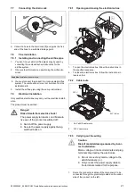
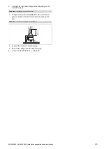
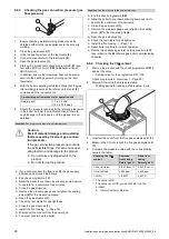
Filling the condensate siphon
C
2
3
1
A
B
1.
Unclip the lower section of the siphon
(1)
from the up-
per section of the siphon
(2)
.
2.
Remove the float
(3)
.
3.
Fill the lower section of the siphon with water up to 10
mm below the upper edge of the condensate discharge
pipe.
4.
Re-insert the float
(3)
.
Note
Check that the float is present in the con-
densate siphon.
5.
Clip the lower section of the siphon
(1)
into the upper
section of the siphon
(2)
.
9.4
Switching on the product
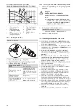
▶
Switch on the product via the main switch installed on-
site.
9.5
Avoiding danger arising from insufficient
water pressure
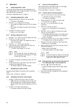
The filling pressure must be between 0.10 and 0.15 MPa
(1.0 and 1.5 bar).
Note
If the heating flow temperature is shown in the
display, press and hold the
and
buttons at
the same time for longer than five seconds, or
temporarily deactivate heating mode in order to
display the pressure.
If the heating installation extends over several storeys,
higher filling pressures may be required to avoid air entering
the heating installation.
If the water pressure falls below 0.05 MPa (0.5 bar), the
value flashes in the display.
If the water pressure falls below 0.03 MPa (0.3 bar), the
product switches off. The display shows 0.0 MPa (0.0 bar).
Fault F22 will be stored in the fault list.
▶
Top up the water in the heating installation to start up the
product again.
◁
The pressure value flashes in the display until a
pressure of 0.05 MPa (0.5 bar) or higher has been
reached.
9.6
Flushing the heating installation for the first
time ("cold")
Note
The complete heating system must be flushed
at least twice: Once with cold water and once
with hot water in accordance with the following
instructions.
1.
Check whether all thermostatic radiator valves and both
service valves on the product are open.
2.
Connect a hose to the drain valve that is located at the
lowest position in the heating system.
3.
Open the radiator valves and the drain valves so that
the water can drain quickly. Start at the next point in the
installation and open the purging valves on the radiators
so that the contaminated water can completely drain.
4.
Close the draining cocks.
5.
Refill the heating system with water.
6.
Check that the expansion relief valve of the heating
system is functioning correctly by turning the handle
on the valve.
7.
Check the pressure in the heating system and top up
with water if necessary.
8.
Close the filling valve and the cold water tap.
Summary of Contents for EASICOM 3 24c
Page 1: ...en Installation and maintenance instructions EASICOM 3 24c 28c 0020239562_04 31 07 2020 ...
Page 54: ......
Page 55: ......

