


Installation 7
0020300877_01 Energy
7
Installation and maintenance instructions
21
7
Installation
7.1
Preparing for installation
▶
Make sure that the existing gas meter and the pipelines
are capable of passing the rate of gas supply required.
▶
Consider the maximum heat output given in DHW mode.
▶
Install the following components:
–
Draining cocks at the lowest points in the heating
installation (
→
current version of "BS 2879")
–
A bypass that is at least 1.5 m away from the product
–
A stopcock in the gas pipe
–
Where applicable, a flow regulator valve to adjust the
flow rate
▶
Install the connection pipes such that they are free from
mechanical stress.
▶
If you use non-diffusion-tight plastic pipes in the heating
installation, ensure that no air gets into the heat gener-
ator circuit.
▶
Only solder connectors if the connectors are not yet
screwed to the service valves.
▶
Only bend connection pipes if they have not yet been
connected to the product.
▶
Flush the heating installation thoroughly before installing
the product.
▶
Check the leak-tightness of the gas valve assembly using
a pressure of
≤
11 kPa (110 mbar).
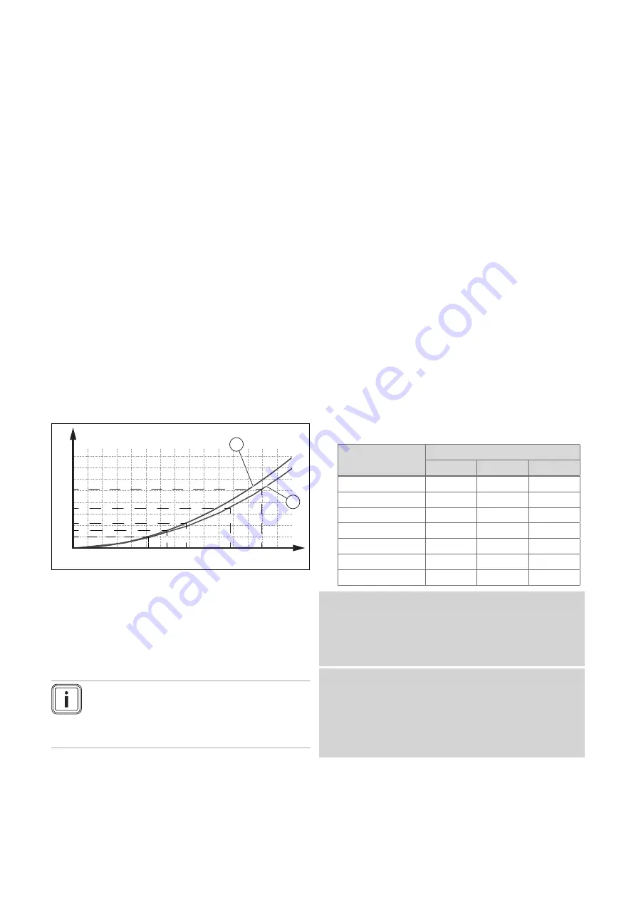
Pressure loss in the product
from the product
0
50
100
150
200
250
300
350
400
0
200
400
600
800
1000 1200 1400
30r
25r
18r
15r
12r
A
B
1
2
A
Flow rate [l/h]
B
Pressure loss [mbar]
1
Pressure loss 12r, 15r,
18r
2
Pressure loss 25r, 30r
The flow rate must not fall below the value in the diagram.
7.2
Flushing the heating installation for the first
time ("cold")
Note
The complete heating system must be flushed
at least twice: Once with cold water and once
with hot water in accordance with the following
instructions.
1.
Check whether all thermostatic radiator valves and both
service valves on the product are open.
2.
Connect a hose to the drain valve that is located at the
lowest position in the heating system.
3.
Open the radiator valves and the drain valves so that
the water can drain quickly. Start at the next point in the
installation and open the purging valves on the radiators
so that the contaminated water can completely drain.
4.
Close the draining cocks.
5.
Refill the heating system with water.
6.
Check that the expansion relief valve of the heating
system is functioning correctly by turning the handle
on the valve.
7.
Check the pressure in the heating system and top up
with water if necessary.
8.
Close the filling valve and the cold water tap.
7.3
Checking the gas meter
▶
Make sure that the existing gas meter is capable of
passing the rate of gas supply required.
7.4
Checking the gas flow rate
The gas flow rate has been set during production and does
not require adjustment. With the front casing fitted check the
gas flow rate of the boiler as follows:
▶
Start up the product with the check programme
P.01
.
▶
In addition, ensure that maximum heat can be dissipated
into the heating system by turning up the room thermo-
stat.
▶
Wait at least 5 minutes until the boiler has reached its
operating temperature.
▶
Ensure that all other gas appliances in the property are
turned off.
▶
Measure the gas flow rate at the gas meter.
▶
Compare the measured values with the corresponding
values in the table.
Qnw from the data
plate
H gas in m
³
/h
Nom.
+5%
−
10%
15.3
1.62
1.70
1.46
18.4
1.95
2.05
1.76
24.7
2.61
2.74
2.35
25.7
2.72
2.86
2.45
28.6
3.03
3.18
2.73
30.6
3.24
3.40
2.92
35.7
3.78
3.97
3.40
Condition
: Gas flow rate not in the permissible range
▶
Check all of the piping and ensure that the gas flow rates
are correct.
▶
Only put the product into operation once the gas flow
rates have been corrected.
Condition
: Gas flow rate in the permissible range
▶
End the check programme
P.01
.
▶
Allow the boiler to cool down by allowing pump overrun to
operate for a minimum of 2 minutes.
▶
Record the boiler maximum gas flow rate onto the
Benchmark gas boiler commissioning checklist.


