background image

1

Instructions for Final Assembly

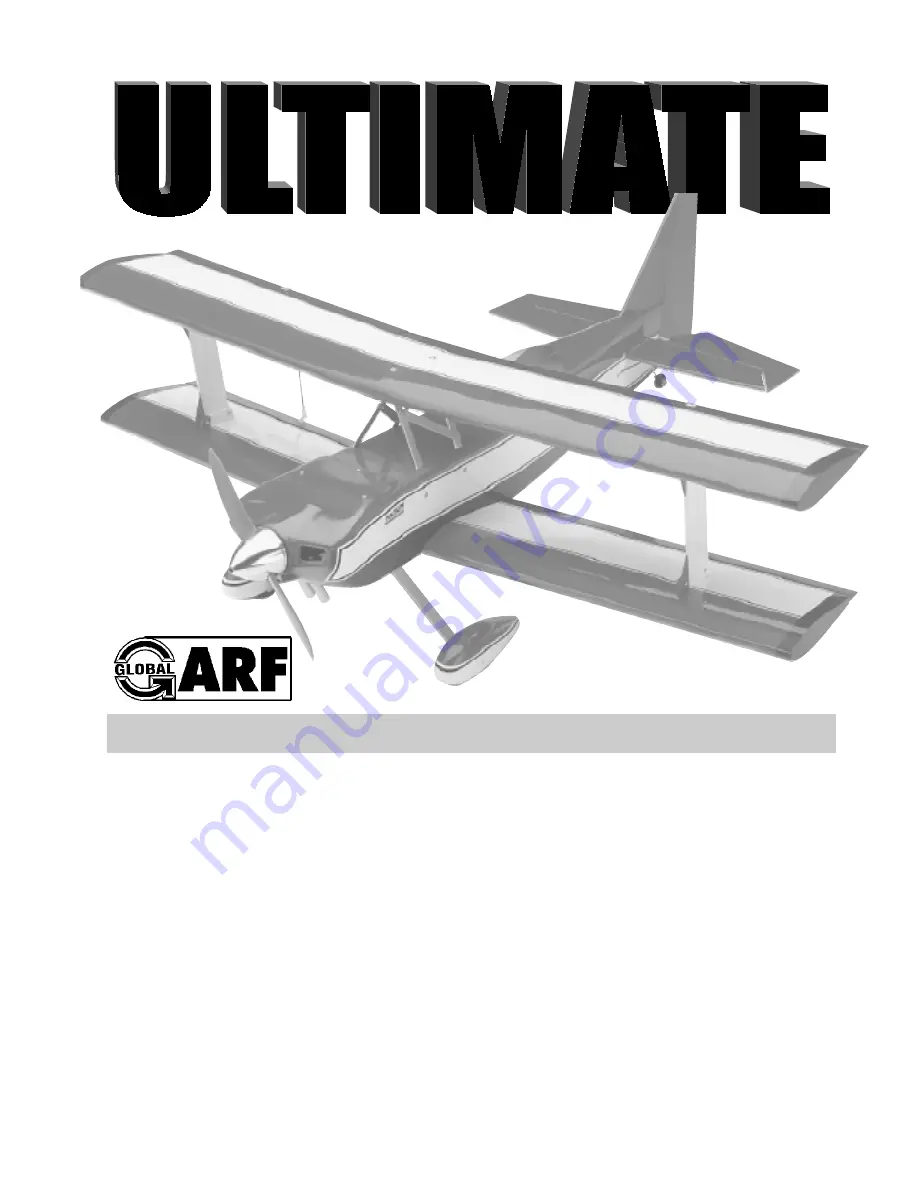
Would you like to fly your own Ultimate Biplane?  Do you want to be flying in a weekend?
Are you ready for an aerobatic 46 size performance biplane?  Then you’ve chosen wisely.
The Global ARF Ultimate was made for you.  Features like an all balsa and plywood built up
airframe, just like you'd do it yourself from a kit.  A generous tail section combined with a
long fuselage moment and swept wings make this an aerobatic performer that you'll always
want to fly.  A super strong metal wing  center cabane system with outer plywood interplane
struts hold everything together when you're performing snap rolls and inverted spins.  To go
along with this we've provided  a prepainted four color cowling, prepainted wheel pants and
a clear molded canopy.  There is no other aerobatic biplane in it's class that is easier to
assemble or that flys better.  We know you’ll enjoy building the Ultimate, but you bought this
airplane to fly.  And that's what it does best.  Set up for sport flying, it’s predictable and
tracks like it's on rails.  Deceivingly easy to fly, change the set-up parameters and you’ll
push the envelope like an experienced airshow performer.  Complete inverted flat spins and
torque rolls like you’ve never performed before!

Version V1.0

3-99

Kit # 123820

 All Contents © Copyright 1999

.46 SIZE AEROBATIC ARF PERFORMANCE BIPLANE

.46 SIZE AEROBATIC ARF PERFORMANCE BIPLANE

.46 SIZE AEROBATIC ARF PERFORMANCE BIPLANE

.46 SIZE AEROBATIC ARF PERFORMANCE BIPLANE

.46 SIZE AEROBATIC ARF PERFORMANCE BIPLANE

Summary of Contents for Ultimate

Page 1: ...along with this we ve provided a prepainted four color cowling prepainted wheel pants and a clear molded canopy There is no other aerobatic biplane in it s class that is easier to assemble or that flys better We know you ll enjoy building the Ultimate but you bought this airplane to fly And that s what it does best Set up for sport flying it s predictable and tracks like it s on rails Deceivingly ...

Page 2: ...ilizer 5 Mounting the Horizontal Stabilizer 6 Vertical Stabilizer Mounting 7 Align the Vertical Stabilizer 7 Mounting the Vertical Stabilizer 7 Top Wing Mounting 7 Align the Top Wing 7 Installing the Interplane Struts 8 Mounting the Top Wing 9 Control Surface Installation 9 Hinge the Elevator Halves 9 Install the Tail Wheel Assembly 9 Hinge the Rudder 10 Install the Tail Wheel 11 Hinge the Bottom ...

Page 3: ...es o 4 2mm x 15mm Machine Screws o 2 600mm Nylon Pushrods o 2 2mm x 100mm Wire Threaded Both Ends o 3 Nylon Clevises one w 1 5mm I D Hole o 1 Nylon Joiner Plate o 2 2 2mm x 10mm Wood Screws o 4 2mm Flat Washers o 1 2mm x 20mm Machine Screw o 1 2mm Hex Nut o 1 Nylon Control Horn w Nylon Back Plate o 2 2mm x 15mm Machine Screws o 1 700mm Nylon Pushrod o 1 2mm x 120mm Wire Threaded Both Ends o 1 2mm ...

Page 4: ...Electric Drill o Assorted Drill Bits o Modeling Knife o Machine Oil or Vaseline o Rubbing Alcohol o Paper Towels o Straight Edge Ruler o Dremel Tool w Assorted Bits o Robart Incidence Meter 404 o Ernst Airplane Stand 157 o Phillips Screwdriver o Flat Blade Screwdriver o Wire Cutters o Pliers o Builders Triangle o 220 Grit Sandpaper o Masking Tape o Scissors FIELD SUPPORT EQUIPMENT NEEDED o Magnum ...

Page 5: ... 2 4mm x 25mm Machine Screws o 2 4mm Washers o 2 4mm Blind Nuts o 1 Place the wing into the wing saddle making sure that the preinstalled dowel in the leading edge of the wing fully engages the predrilled hole in the forward bulkhead in the fuselage Push the wing as far forward as possible The leading edge should fit tight against the bulkhead o 2 Using a ruler and pen measure and place a mark on ...

Page 6: ... Remove the doubler and using a mod eling knife carefully remove the covering from just inside the outline o 11 Mix up a small amount of Kwik Bond 5 Minute Epoxy and use it to glue the wing doubler to the wing Allow the epoxy to fully cure o 12 Remove the wing and drill out the holes through the doubler using a 5 32 drill bit Use the holes already drilled through the wing as a guide and drill down...

Page 7: ...ne where it and the fu selage sides meet Do this on both the right and left sides and top and bottom of the stabi lizer o 7 Remove the stabilizer Using the lines you just drew as a guide carefully remove the covering from between them using a model ing knife See photo 5 below Figure 2 Figure 3 o 5 When you are satisfied with the align ment hold the stabilizer in place with T pins or masking tape b...

Page 8: ...ligned correctly mix up a generous amount of Kwik Bond 30 Minute Epoxy Apply a thin layer to the mounting slot in the top of the fuselage and to the sides and bottom of the vertical stabilizer mounting area Set the stabilizer in place and realign Double check all of your measurements once more before the epoxy cures Hold the stabilizer in place with T pins or masking tape and remove any excess epo...

Page 9: ...led wing hold down holes in the top wing These holes are located down the centerline of the wing The forward hole is located 7 in front of the trailing edge and the rear hole is located 3 5 8 in front of the trailing edge Remove the covering from both the top and bottom of the holes o 7 Mount the top wing to the aluminum cabane struts using the 3mm x 50mm machine screw in the front the 3mm x 35mm ...

Page 10: ...ne strut and the wing We have provided a hardwood cabane shim D 31 for this purpose MOUNTINGTHETOPWING o 16 When completely satisfied with the alignment of the top wing use threadlock on all of the metal cabane screws and nuts and tighten them completely to lock the wing s alignment in place o 17 Using a pen draw a line on each side of the outer interplane struts where they meet the bottom surface...

Page 11: ...re 7 below Figure 7 o 6 Apply oil or Vaseline to the hinge bear ing to prevent epoxy from gluing the bearing solid to the tail wheel wire o 7 Mix up a small amount of Kwik Bond 5 Minute Epoxy Apply the epoxy to only those parts of the tail wheel wire that will be glued to the rudder being careful not to get any epoxy on the nylon bearing Pack epoxy into the hole you drilled in the leading edge of ...

Page 12: ...orque rod and the trailing edge of the wing See photo 16 below Photo 16 The waxed paper will prevent epoxy from gluing the torque rod to the trailing edge of thewing o 16 Mix up a small amount of Kwik Bond 30 Minute Epoxy Apply a thin layer of ep oxy to the aileron torque rod Also use a tooth pick and pack epoxy into the predrilled hole in the aileron o 17 Slide the aileron and it s hinges into th...

Page 13: ...ts completely If using an engine equipped with a re mote needle valve we recommend mounting the needle valve to the engine prior to installing the engine on the motor mount beams ALIGNINGTHEMOTORMOUNT o 5 The engine is mounted sideways on the firewall Using a ruler and pen measure and draw a vertical centerline on the firewall o 6 Measure down from the top of the fu selage 1 1 2 and draw a horizon...

Page 14: ...oth each end of the two tubes This will prevent the fuel line from being cut o 3 Push the two aluminum tubes through the rubber stopper until 1 2 protrudes from the front of the stopper Slide the 20mm di ameter front squash plate over the tubes at the front of the stopper and slide the 18mm diam eter rear squash plate over the tubes at the rear of the stopper Insert the 3mm x 20mm ma chine screw i...

Page 15: ...cate and drill a 3 32 hole through the firewall for the throttle pushrod wire to pass through The hole should be level with the throttle arm but moved over enough to clear the fuel tank Be careful not to drill into the fuel tank o 3 Slide the pushrod wire through the hole and into the fuselage Attach the clevis to the throttle arm Use a pair of pliers and make the necessary bends in the wire so it...

Page 16: ...ter wheel onto one 4mm x 35mm axle screw The wheel should go on with flat side of the hub first o 5 Slide two 4mm nylon spacers over the axle screw and up against the wheel Thread one 4mm hex nut onto the axle screw o 6 Tighten the hex nut against the nylon spacers as tight as it can be but still allow the wheel to spin free on the axle Secure the nut in place by carefully applying a couple of dro...

Page 17: ...s and using a modeling knife remove the cov ering from just inside the lines o 4 Mix a small amount of Kwik Bond 5 Minute Epoxy and glue the plates in place Allow the epoxy to cure completely o 5 Install the servo using the wood screws provided with your radio system Drill 1 16 pilot holes through the plates before install ing the screws This will help prevent the wood from splitting INSTALLINGTHE...

Page 18: ...front of the fuselage See photo 32 below Because the size of servos differ you may need to adjust the size of the precut open ings You may also need to use a modeling knife and cut a groove to allow room for the servo wires o 4 Install the servos using the wood screws provided with your radio system Drill 1 16 pilot holes through the tray before in stalling the screws This will help prevent the wo...

Page 19: ...enter With the carburetor barrel fully closed tighten the set screw in the adjustable servo connector o 5 Removetheexcessthrottlepushrodwire using wire cutters See photo 33 below Photo 33 o 6 Test the movement of the throttle pushrod Full forward stick and full forward trim should result in the carburetor barrel opening completely Full down stick and full forward trim should result in the approxim...

Page 20: ...vo compart ment from the rear bulkhead o 9 Using a modeling knife cut off the pushrod housing at this mark o 10 Slide the pushrod back into the pushrod housing Snap the clevis onto the rud der control horn and use a couple of pieces of masking tape to hold the rudder in neutral o 11 Locate a long servo arm and using wire cutters remove all but one of the arms Install the L bend in the 85mm wire in...

Page 21: ...center of the nylon joiner plate Slide a 2mm washer onto the 2mm x 20mm machine screw Slide the screw through the center hole of the nylon joiner plate o 5 Slide a second 2mm washer onto the machine screw and then thread on the 2mm nut Tighten the nut completely and secure it in place using Kwik Bond Thin C A Let the C A cure completely and double check to en sure the screw and nut do not move We ...

Page 22: ...d remove the masking tape from the elevator halves See photo 37 below Photo 37 o 19 Move the elevator halves up and down There may be some flex present in the pushrod just before it gets to the elevator servo If so position one pushrod support D 32 between the two pushrod housings and the servo tray Using a small amount of Kwik Bond 5 Minute Epoxy glue the hous ings to the support and the support ...

Page 23: ...g tape o 3 Using a pen place a mark on both sides of the canopy at the front and back Place the marks where the canopy meets the bottom of the black stripe on the fuselage sides o 4 Using a 3 32 drill bit drill four mounting holes through the canopy only Locate two holes on each side near the cock pit Use the photo below for reference See photo 40 below Photo 40 o 5 Secure the canopy in place usin...

Page 24: ...Locate and the areas of the cowl that need to be removed for access to the high and low speed needle valves glow plug muffler and if necessary engine head clearance o 9 Remove the cowl and make these cut outs using a Dremel Tool with a sanding drum attachment Holes for the needle valves can be cut using a drill bit We highly suggest the use of a Dubro Fuel Filler Valve to fuel the airplane This sh...

Page 25: ...ve but less stable Moving the balance point forward will cause the Ultimate to be more stable but less responsive Do not fly the Ultimate be yond the recommended balance range or an uncontrollable crash could result LATERALBALANCE After you have balanced your Ultimate on the C G you must laterally balance it Doing this will help the airplane track bet ter in vertical maneuvers and loops o 1 Turn t...

Page 26: ...OTES ____________________________________________________ ______________________________________________ ______________________________________________ ______________________________________________ _____________________________________________ ______________________________________________ ______________________________________________ _____________________________________________ _______________...

Page 27: ...Nose drops If C Remove nose weight Yaw Into wind do inside A Wings level throughout If A Trim is correct loops using only elevator B Yaws to right in both If B Add left rudder trim Repeat tests doing inside and outside loops outside loops from C Yaws to left in both If C Add right rudder trim inverted entry inside and outside loops D Yaws to right on inside If D Add left aileron trim and left on o...

Page 28: ...CIFICATIONS Length 47 25in Span 52in Area 570sq in Flying Weight 5 5 5lbs Engine 45 53 2 stroke 52 60 4 stroke Radio 4 channel ü All Wood Construction ü Prebent Aluminum Landing Gear ü Prepainted Fiberglass Cowling ü Prepainted Molded Wheel Pants ü Clear Molded Canopy ü Lightweight and Fast for Big Performance ...

Page 29: ...o goalongwithit ü All Wood Construction ü Custom Spinner ü Prepainted Fiberglass Cowling ü Molded Wheel Pants ü Clear Molded Canopy ü Incredible Aerobatic Performer SPECIFICATIONS Length 42in Span 52in Area 362sq in Flying Weight 5 5 5lbs Engine 45 53 2 stroke 52 60 4 stroke Radio 4 channel ...

Page 30: ...hit SPECIFICATIONS Span 59in Area 620sq in Empty Weight 3 5lbs Engine 40 46 2 stroke 52 60 4 stroke Radio 4 5 channel ü All Wood Construction ü Ready for Retracts ü Prepainted Fiberglass Cowling ü Prepainted Wheel Pants for Fixed Gear ü Clear Molded Canopy ü Big Pattern Performance In a Midsize Package ...

Page 31: ..._____________________________ 11 How does this kit compare to similar kits by other manufacturers o Better Than o As Good o Not as Good 12 Please list any other comments or suggestions you have _________________________________ _________________________________ _________________________________ _________________________________ 1 Kit Ultimate Biplane 46 123820 2 Where did you learn about this kit ...

Page 32: ...3 2 Fold along dotted line Fold along dotted line Place Stamp Here Global Hobby Distributors Attn Customer Service Department 18480 Bandilier Circle Fountain Valley CA 92728 ...

Reviews: