background image

Global Power Technologies 

SERVICE AND MAINTENANCE 

05585 rev11 | Model 8550-SD 

Page 29 of 53 


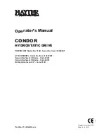
Figure 15 – Burner System Components 

With the burner plate assembly removed, examine the exhaust stack through the Power Unit, 

remove any obstructions and check for corrosion.  
If the exhaust stack is corroded, it must be replaced as follows: 

1.


Remove the converter shroud which covers the lower portion of the heat pipes. This can be 

accomplished without removing the heat pipe support frame. 

NOTE:  Turn off the fuel supply at the external valve before performing service checks on the 

fuel system. 


2.


Remove the four nut-and-spring assemblies that hold down the converter mounting ring. 

Before removing the converter mounting ring, mark its position so that it can be reinstalled in the 

same position. 

3.


Lift the exhaust stack off. 

Before replacing the exhaust stack, check if the high temperature exhaust gasket is still in good 

condition and replace if necessary. To replace, t

ighten the spring assemblies that are holding the 

converter mounting ring in place until the springs are solid, then back off by about 5 turns (1/4 inch 

or 6 mm). 

Always apply a high temperature nickel-based, anti-seize compound to the threads on the venturi 

before installing it. It is not necessary to tighten the venturi more than hand tight. 

Summary of Contents for 8550-SD

Page 1: ...Global Power Technologies www globalte com Model 8550 SD Thermoelectric Generator OPERATING MANUAL ...

Page 2: ......

Page 3: ... CUSTOMER LOAD 20 5 SERVICE AND MAINTENANCE 21 5 1 POWER CHECK 21 5 2 BASIC SERVICE 23 5 3 COOLING SYSTEM 24 5 4 FUEL SYSTEM 26 5 5 BURNER SYSTEM 28 5 6 SPARK IGNITION SI 30 5 7 OVERTEMPERATURE SHUTDOWN SYSTEM 32 5 8 AUTOMATIC SHUT OFF SO 33 5 9 POWER UNIT TESTING 35 6 TROUBLESHOOTING 37 7 PARTS LISTS 39 8 6720 VOLTAGE LIMITER FOR MODEL 8550 SD TEG 44 8 1 PRODUCT APPLICATION 44 8 2 OPERATION 44 8 ...

Page 4: ...er System Components 29 Figure 16 Spark Ignition System Wiring 30 Figure 17 Spark Ignition Components 31 Figure 18 Overtemperature Shutdown System 33 Figure 19 Automatic Shut off Components 34 Figure 20 Model 8550 SD TEG Parts List 1 of 2 39 Figure 21 Model 8550 SD TEG Parts List 2 of2 40 Figure 22 Fuel System Parts List 42 Figure 23 6720 Voltage Limiter 44 Figure 24 6720 Limiter Main Parts 46 Fig...

Page 5: ...Thermoelectric Generator is designed to combust gaseous fuels which will result in combustion products including heat carbon dioxide and water vapour and may contain traces of carbon monoxide unburned hydrocarbons and nitrous oxides Emissions from combustion will depend on generator set up and operation as well as the composition of the gas feed Ensure that gas supplied meets Global Power Technolo...

Page 6: ... by Global Power Technologies GPT All rights reserved No part of this manual may be reproduced without permission in writing from GPT except by a reviewer who may quote brief passages or reproduce illustrations in a review with appropriate credit nor may any part of this manual be reproduced stored in a retrieval system or transmitted in any form or by any means electronic photocopying recording o...

Page 7: ... Power Technologies Power Unit The hermetically sealed portion of the generator that contains the thermoelectric materials Matched Load A condition of load where the load voltage of the generator is one half of the open circuit voltage Optimum Load A condition of load where the power output of the generator is maximized Power Conditioner A broad term used to describe an electronic device attached ...

Page 8: ...e inside of the cabinet door When contacting GPT indicate both the complete Model Number and Serial Number of your TEG Figure 1 Data Plate The information indicated on the data plate are as follows Design Altitude Maximum permitted altitude that the TEG should be operated at Fuel Input Rating Maximum permitted energy rate to the generator Inlet Pressure Minimum and maximum levels of inlet fuel pre...

Page 9: ...r and temperature recorded during the factory acceptance test This is the maximum power unit power that can be expected from the TEG under similar conditions Voltage Power unit voltage recorded during factory acceptance test Burner Fuel Pressure Burner fuel pressure recorded during factory acceptance test The Model 8550 SD TEG s model number can be interpreted as follows Figure 2 Model Number Expl...

Page 10: ...bstruct the flow of wind choose a site on the windward side at least 45 feet 14 m away from the building or object or on the roof if possible Always follow local regulations when placing the TEG near buildings and fuel tanks 3 1 3 FUEL SUPPLY The fuel system on each TEG unit is designed for either propane or natural gas Check the Data Plate on inside of the TEG cabinet to verify the type of fuel t...

Page 11: ...oint in excess of 0 C 32 F at 170 kPag 25 psig 3 Shall not contain more than 115 mg Sm3 2 approx 170 ppm of H2S 3 4 Shall not contain more than 60 mg Sm3 approx 88 pmm of Mercaptan Sulphur 5 Shall not contain more than 200 mg Sm3 approx 294 ppm of total Sulphur 6 Shall not contain more than 10 CO2 and or N2 by volume nor vary by more than 1 CO2 and or N2 during operation 7 Shall not contain more t...

Page 12: ...ate 1 Check the TEG for any damage that may have occurred during shipping If the TEG shows any sign of damage contact Global Power Technologies to report it Do not proceed with the installation 2 Check and re tighten any bolts that may have loosened 3 Remove the tie wraps that clamp the ends of the heat pipes to the support ring CAUTION Failure to remove the tie wraps can cause the heat pipes to c...

Page 13: ...ore than 3 then proceed to the next step Figure 4 TEG Stand WARNING Operation of TEG on an unstable or non level base or in locations where cooling air flow may be obstructed will cause overheating of the TEG 3 3 INSTALLING THE RELAY ASSEMBLY The Shutdown Relay Assembly is shipped inside the TEG cabinet To install 1 Thread the male end of the Relay Assembly into the bottom of the Shut off Valve on...

Page 14: ... Spark Igniter Electrode through the fitting on the bottom of the burner until it touches inside then pull back by approximately 1 8 inch 3 mm This should leave 2 24 to 2 40 inches 57 to 61 mm extruding beyond the fitting refer to Figure 5 2 Gently tighten the nut on the fitting to maintain the position of the electrode 3 Connect the terminal lug of the high voltage cable to the end of the Spark I...

Page 15: ...TING FOR ALTITUDE The burner fuel pressure supplied on the TEG and marked on the data plate is set for the factory altitude or site elevation of 2460 ft 750 m At the factory s elevation the fuel pressure should be in the range of 16 to 22 psi 110 to 150 kPa for propane or 6 to 10 psi 41 to 69 kPa for natural gas If the TEG s installation site is at a similar altitude check the burner fuel pressure...

Page 16: ...that adjustment is required for your site s altitude by counting vertically from the Factory Elevation mark at 0 psi kPa Enter this number on the Start up Data Sheet For example If your TEG will be installed at a site with an altitude of 2460 ft 750 m increase your burner fuel pressure by 2 61 psi 18 kPa from the factory setting Figure 7 Altitude Adjustment ...

Page 17: ... This will also need to be done for power adjustments NOTE Use the Start up Data Sheet located at the end of this manual during the start up process It helps simplify starting heating up and making power adjustments 4 1 1 DETERMINE SET POWER Determine the required Set Power before proceeding with Start up Set Power is the power to which the TEG must be set at your ambient conditions so that it gen...

Page 18: ...0 26 11 0 10 21 30 39 50 59 70 79 90 99 109 12 4 42 31 20 6 7 18 27 36 46 55 66 75 86 95 106 15 5 47 35 24 9 3 14 23 32 42 52 63 72 82 91 100 18 6 51 38 27 13 0 10 19 30 39 48 59 68 79 88 99 21 7 53 40 29 15 2 9 18 28 37 46 57 66 77 86 97 24 8 56 44 3 8 4 7 16 27 35 45 55 64 75 84 95 Table 2 Corrected Air Temperature for Wind in miles per hour and F 2 Using the corrected air temperature as determi...

Page 19: ...wer Unit voltage during start up Connect the second voltmeter across Terminals 6 and 7 of TB 1 This will measure the Power Unit current 1 mV 1 Amp Follow these steps to start up the Model 8550 SD TEG 1 Turn on the fuel supply to the TEG and observe the fuel pressure at the fuel pressure gauge Refer to the Start up Data Sheet and compare the observed fuel pressure to the adjusted fuel pressure as d...

Page 20: ... Burner Run Valve is closed down 4 Open the Automatic Shut Off valve by pressing the button with one hand Keep this button pressed Do not release until instructed Step 8 The Spark Igniter should start clicking followed by a series of popping sounds from the unit as the burner ignites The Power Unit voltage will start to rise slightly 5 Continue to hold down the button If ignition does not occur wi...

Page 21: ...wn WARNING Proceed to the Heat Up and Power Adjustment section as soon as the automatic shut off valve remains open Failure to do so may overheat the Power Unit 4 1 3 HEAT UP AND POWER ADJUSTMENT It is normal for the heat pipes to make a crackling sound as they start to operate Once the burner is operating the Power Unit voltage will climb rapidly to the TEG s voltage setpoint set to 27 1 V at the...

Page 22: ...t Up Data Sheet If the power level is less than 70 of Set Power after 30 minutes the fuel pressure may be too low Wait until the power level has stabilized and make the necessary adjustment NOTE Keep the cabinet door closed as much as possible during the warm up period until the Power Unit output power stabilizes It takes about one full hour for the power to stabilize 12 Review the recorded data o...

Page 23: ...the air shutter by another 1 8 inch 3 mm wait 10 minutes and then take another power reading Continue closing the air shutter by 1 8 inch 3 mm and checking the power every ten minutes until the power no longer rises then proceed to the next step If the new power reading is lower than the initial reading open the Air Shutter by 1 8 inch 3 mm past the initial setting wait 10 minutes then take anothe...

Page 24: ... power conditioner output to the desired customer voltage as outlined in Section 9 To apply customer load 1 Connect the customer load to the TEG at terminals 2 and 4 of terminal block TB 1 2 Turn the circuit breaker on the power conditioner to the ON position 3 Close and latch the cabinet WARNING The Power Unit output must always remain connected with the Power Conditioner A System Performance Log...

Page 25: ...Power and the System Performance Log to make sure that the TEG was left operating at Set Power during the last maintenance visit Perform a power check by doing the following 1 Check the Power Unit voltage at Terminals 6 and 4 of TB 1 2 Check the Power Unit current at terminals 6 and 7 of TB 1 The Current Shunt rating is 50 Amps 50 mV 3 Calculate the Power Unit output power by multiplying the Power...

Page 26: ...it is essential that the TEG be supplied with a fuel of constant heating value Poor cooling by heat pipes Check to make sure that the Heat Pipe fins are not obstructed by debris or dust Check that the Heat Pipe ends are warm Test the cooling system as outlined in Sections 6 3 Change in customer load An overloaded TEG can see a minor to severe decline in output power and voltage Verify that the con...

Page 27: ...e complete Burner System for obstructions and damage as outlined on Section 6 5 If after servicing and restarting the Power Unit still does not come to Set Power a change in the fuel quality is likely the cause Increase the fuel pressure to obtain Set Power being careful not to exceed the maximum VOC and RINT as determined in Section 6 9 It will take 10 minutes for a change in fuel pressure to tak...

Page 28: ... are serviceable components and should be replaced to prolong the life of the TEG If you find any evidence of a poorly functioning heat pipe please contact GPT 5 3 1 HAND INSPECTION Before performing this inspection ensure that the TEG has been operating for at least one hour If possible choose a day that is calm and not windy This method involves touching the heat pipes with bare hands This is a ...

Page 29: ...he requirements of the hand temperature inspection i e heat pipes that are not noticeably warm up to 2 inches 50 mm from the tip Tool required thermocouple meter range up to 150 C 300 F example Digital Multimeter with K type thermocouple adapter surface temperature probe 50mm 2 in long 5 mm 0 2 in diameter K type thermocouple probe Keep the TEG operating for at least an hour in calm weather condit...

Page 30: ...pe that is operating at a temperature much lower than the rest of the heat pipes Replacement of heat pipes should only be done by a factory trained technician consult GPT for heat pipes replacement Remove and replace any heat pipe that is visually damaged CAUTION Do not operate the TEG if it has a damaged heat pipe 5 4 FUEL SYSTEM WARNING Turn off the fuel supply at the external valve before perfo...

Page 31: ...hat may have collected in the bowl 3 After the bowl has drained close the drain cock 5 4 2 CHANGING THE FUEL FILTER To change the fuel filter 1 Remove the 4 socket cap screws that hold the bottom bowl on the pressure regulator 2 Remove the bottom bowl and replace the filter element 3 Check and replace the gasket if needed 4 Carefully reassemble the regulator ensuring that the needle valve spring i...

Page 32: ...he fuel orifice as per Section 6 4 and allow the burner to cool Once the burner has cooled down identify and locate the components from Figure 15 proceed with disassembly as follows 1 Remove the venturi and air shutter assembly from the burner plate by turning the venturi which is threaded into the burner plate assembly counterclockwise 2 Remove the air shutter from the venturi by closing the air ...

Page 33: ...service checks on the fuel system 2 Remove the four nut and spring assemblies that hold down the converter mounting ring Before removing the converter mounting ring mark its position so that it can be reinstalled in the same position 3 Lift the exhaust stack off Before replacing the exhaust stack check if the high temperature exhaust gasket is still in good condition and replace if necessary To re...

Page 34: ...ectrode or until the Pressure Switch is opened Figure 16 Spark Ignition System Wiring The Control Module contains a 2 Volt 2 5 Amp hour rechargeable battery and a battery charger A new fully charged battery provides approximately 16 hours of continuous sparking capability Twenty minutes of recharging is sufficient for one start cycle A completely discharged battery requires 16 hours of charging to...

Page 35: ... that there is a 1 8 inch 3 mm gap to the TEG cabinet Then touch the orange wire connector to the Pressure Switch Arcing should occur at the gap at the rate of about one per second If arcing occurs the system is functioning well WARNING Do not touch the tip of the orange wire or allow it to come in contact with other electrical connections 6 Check the Pressure Switch The switch should close at fue...

Page 36: ...es the thermostat fuses and is powered directly from the power unit If all six fuses are intact and the power unit voltage is above 12 5 Volts this Module will provide 12 Volts to energize the Shutdown Relay Shutdown Relay Assembly This assembly is situated between the burner thermocouple and the shut off valve When energized it allows the thermocouple signal to pass through If an overtemperature ...

Page 37: ...fuse Replace all underperforming heat pipes as necessary If any shutdown fuse repeatedly opens before the TEG fully heats up the corresponding thermostat is likely damaged and should be replaced 5 8 AUTOMATIC SHUT OFF SO The Automatic Shut Off system is designed to turn off the fuel supply to the TEG in the event of a flame outage The thermocouple will hold open the shut off valve as long as good ...

Page 38: ...nect the thermocouple fitting from the Shutdown Relay Assembly Using a voltmeter measure the voltage between the cap in the center of the thermocouple fitting and the sensor case A healthy thermocouple will have a voltage between 15 and 30 millivolts If the thermocouple signal falls below this range or if no continuity is observed then the thermocouple should be replaced NOTE When replacing the th...

Page 39: ...ting for the past 12 hours 1 Measure and record the Power Unit current I at terminals 6 and 7 of TB 1 2 Attach a voltmeter to read the Power Unit voltage at terminals 6 and 4 of TB 1 The voltmeter leads must be attached to these terminals because you will need both hands free to do the open circuit test 3 Measure and record the Power Unit loaded voltage VL Record the momentary open circuit Power U...

Page 40: ...its are 56 5 Volts for open circuit voltage and 1 45 Ohms for internal resistance If the Power Unit does not produce Set Power and problems with the Burner System Fuel System and Cooling System have been ruled out increase the fuel pressure until one of the above limits or Set Power is reached Remember that it will take at least 10 minutes for a change in fuel pressure to take full effect See also...

Page 41: ...re to the TEG 4 6 Burner Run Valve left open before starting Close the Burner Run Valve 5 1 2 Fuel filter dirty Drain the regulator sediment 6 4 Replace the fuel filter 6 4 2 Fuel pressure adjustment incorrect Adjust the burner fuel pressure 5 1 2 Fuel Orifice plugged Replace the fuel Orifice 6 4 3 Fuel Orifice size incorrect 6 4 3 Air Shutter adjustment incorrect Tune the Air Shutter 5 1 4 Incorr...

Page 42: ...e signal Troubleshoot Shut off System 6 8 Shut off Valve malfunctioning 6 8 Low output power or output voltage Set Power incorrect Determine proper Set Power for ambient conditions 5 1 1 Heat Pipes not adequately cooling power unit Maintain and or replace Heat Pipes 6 3 Fuel pressure adjustment incorrect Adjust Burner fuel pressure 5 1 2 Air shutter adjustment incorrect Adjust Air Shutter 5 1 4 Ou...

Page 43: ...bly Water Methanol Orange tip 22896 Heat Pipe Assembly Water Ethanol Black tip 22897 Heat Pipe Assembly Methanol White tip A8 6396 Heat Pipe Clip A9 6397 Support Bracket A10 6398 Converter Shroud NOTE The Heat Pipe Assembly type will vary depending on the TEG type as follows Warm Ambient uses 12 each of 22895 orange tip Cold Ambient uses 6 each of 22897 white tip alternating with 6 each of 22896 b...

Page 44: ...Global Power Technologies PARTS LISTS 05585 rev11 Model 8550 SD Page 40 of 53 MODEL 8550 SD TEG PARTS LIST 2 of 2 Figure 21 Model 8550 SD TEG Parts List 2 of2 ...

Page 45: ...ner Assy B9 177 Thermocouple 24 B10 22385 Fuel System Natural Gas 22384 Fuel System Propane B11 6978 Shutdown Relay Assembly B12 67289 Spark Igniter Module Assembly 27019 Battery 2V 2 5 AH D size inside B12 B13 5238 Shunt 50 Amp 50 mV Bach 6709 B14 2110 Terminal Block 8 Position B15 6963 Shutdown Module Overtemperature B16 6768 Spark Electrode Assembly B17 6418 Venturi B18 6968 Stand Off Hex 1 4 2...

Page 46: ...Global Power Technologies PARTS LISTS 05585 rev11 Model 8550 SD Page 42 of 53 FUEL SYSTEM PARTS LIST Figure 22 Fuel System Parts List ...

Page 47: ...er Natural Gas B4SMA 400L C10 5048 Tee 1 4 Female NPT 101 B Brass C11 476 Elbow 90 1 4 Male NPT Brass C12 176 Valve Shut Off C13 6471 Switch Pressure 1 5 PSI C14 501 Nipple Hex 1 4 NPT x 1 1 2 Brass C15 2100 Manifold Block C16 406 Gauge Pressure 0 30 PSI C17 432 Plug Hex Hd 1 8 27 NPT Brass C18 376 Nipple 1 4 NPT x 2 Lg Brass C19 22359 Regulator 3 20 PSI Fisher 67CFR C20 2360 Adaptor 11 4 MNPT X 1...

Page 48: ...se current protection from customer load connections Provide a Voltage Sensing Relay VSR that can be used for Low Voltage Alarm and or Voltage Good contacts in customer applications 8 2 OPERATION 8 2 1 OUTPUT VOLTAGE ADJUSTMENT Do not adjust the voltage limiter output voltage until the TEG is set up and operating in accordance with Section 5 of this manual 1 Ensure that the TEG has been running fo...

Page 49: ...the following procedure 1 Ensure the TEG has been running for at least an hour to stabilize 2 Disconnect all customer load connections from terminals 2 and 4 of TB 1 3 Connect a voltmeter across terminal 2 and terminal 4 of TB 1 4 Connect a multimeter across the COM and NC terminals of the VSR Control Board within the 6720 Limiter Set the multimeter to measure continuity or resistance 5 Using a sm...

Page 50: ...TER PARTS LIST Figure 24 6720 Limiter Main Parts Item Part No Description 1 20184 Cover Assy Limiter 8550 not shown order separately 2 3154 Heat Sink Assy 3 116 Resistor 2 Ohm 300 Watts 10 4 59056 Control VSR Board 24 Volt 5 61042 Driver Board 6 284 Circuit Breaker 30 Amp 7 6714 Terminal Block 3 Pole Heavy Duty 8 2580 Output Diode ...

Page 51: ... is not rated to supply more than 30 amps of current to the load If total circuit resistance is less than 0 5 ohms then the 1000 watt variable resistor in the CP box should be wired in series with the circuit and adjusted so that current does not exceed 30 amps 9 1 METER The dual scale meter displays voltage at the terminal block and current when the PUSH TO READ AMPS button is depressed The meter...

Page 52: ...he tap to the right 9 3 2 PARALLEL By connecting the 1000 Watt resistor parallel to the TEG smaller levels of power may be delivered to the CP load This is sometimes required to reduce hot spots on the anode With the tap located at the right side of the resistor the output power will be zero As the tap is moved to the left the power to the CP load is increased The change from series to parallel co...

Page 53: ...9 Mounting Bracket Resistor 3 6594 Cover Assembly Resistor 4 6608 Slide Resistor 5 5014 Bushing Universal 1 6 6634 Box 8550 Cathodic Protection 7 6714 Terminal Block Heavy Duty 3 Pole 8 6226 Meter 0 50 mV DC 2 5 Custom Scale 9 6221 Meter Face 30V 30A 10 6217 Shunt Type 766 30 Amp 50mV 11 3192 Plug Bumper 12 23 Grommet Rubber 7 16 13 2284 CP Meter Assembly Panel Meter 6226 comes with a blank face p...

Page 54: ...below Figure 29 Model 8550 SD TEG Dimensions WEIGHT AND DIMENSIONS Diameter of Top 61 in 155 cm Overall Height 40 in 102 cm Length of Lower Cabinet 18 in 46 cm Width of Lower Cabinet 18 in 46 cm Height of Lower Cabinet 17 in 44 cm Weight with Power Conditioner 225 lb 102 kg ELECTRICAL SPECIFICATIONS Power Rating at 20 C Output Adjustment Range 480 Watts 12 Volts 12 Volt Models 11 4 12 6 Volts 550 ...

Page 55: ...gas The cold junction of the thermocouples is maintained at 235 F 163 C by an array of heat pipes that transfer the heat to the ambient air The cold junction of the thermocouples is maintained at a lower temperature 163 C or 235 F by an array of heat pipes that transfer the heat to the ambient air by natural convection Each heat pipe is hermetically sealed and contains a measured amount of fluid i...

Page 56: ... Operating voltages outside the nominal 24 to 30 Volt range are best achieved by connecting a DC to DC Converter to the output of the TEG Nominal 12 Volt and 48 Volt DC DC Converter options are available for the Model 8550 SD TEG Consult GPT for assistance with finding the best system to suit your application The available power of a Model 8550 SD TEG is also a function of the amount of cooling su...

Page 57: ...Global Power Technologies APPENDIX C SYSTEM WIRING DIAGRAM 05585 rev11 Model 8550 SD Page 53 of 53 APPENDIX C SYSTEM WIRING DIAGRAM Figure 32 Model 8550 SD TEG Wiring Diagram ...

Page 58: ...t Temperature Ignition Fuel Pressure Corrected Air Temperature Operating Fuel Pressure Wind Speed Site Elevation Set Power at Corrected Temperature Corrected Fuel Pressure for Elevation POWER LEVELS Time Burner Fuel Pressure Voltage V Current A Power W Start Time Start 15 minutes 30 minutes 40 minutes 50 minutes 60 minutes ...

Page 59: ...05585 rev11 Model 8550 SD TEG Performance Log MODEL NO SERIAL NO FUEL TYPE ...

Page 60: ...05585 rev11 Model 8550 SD TEG Performance Log MODEL NO SERIAL NO FUEL TYPE ...

Page 61: ...6 F Good TC TD TA TC If 20 C 36 F Replace TC TD If 15 C 27 F Replace 1 2 3 4 5 6 7 8 9 10 11 12 Hand temperature inspection of Model 8550 SD TEG heat pipes is done to check that the heat pipe is warm up to 2 inches 50 mm from the tip If the inspection satisfies the hand inspection as per Section 3 5 1 the detailed inspection described in Section 3 5 2 is not required Heat Pipe Geographic Orientati...

Reviews: