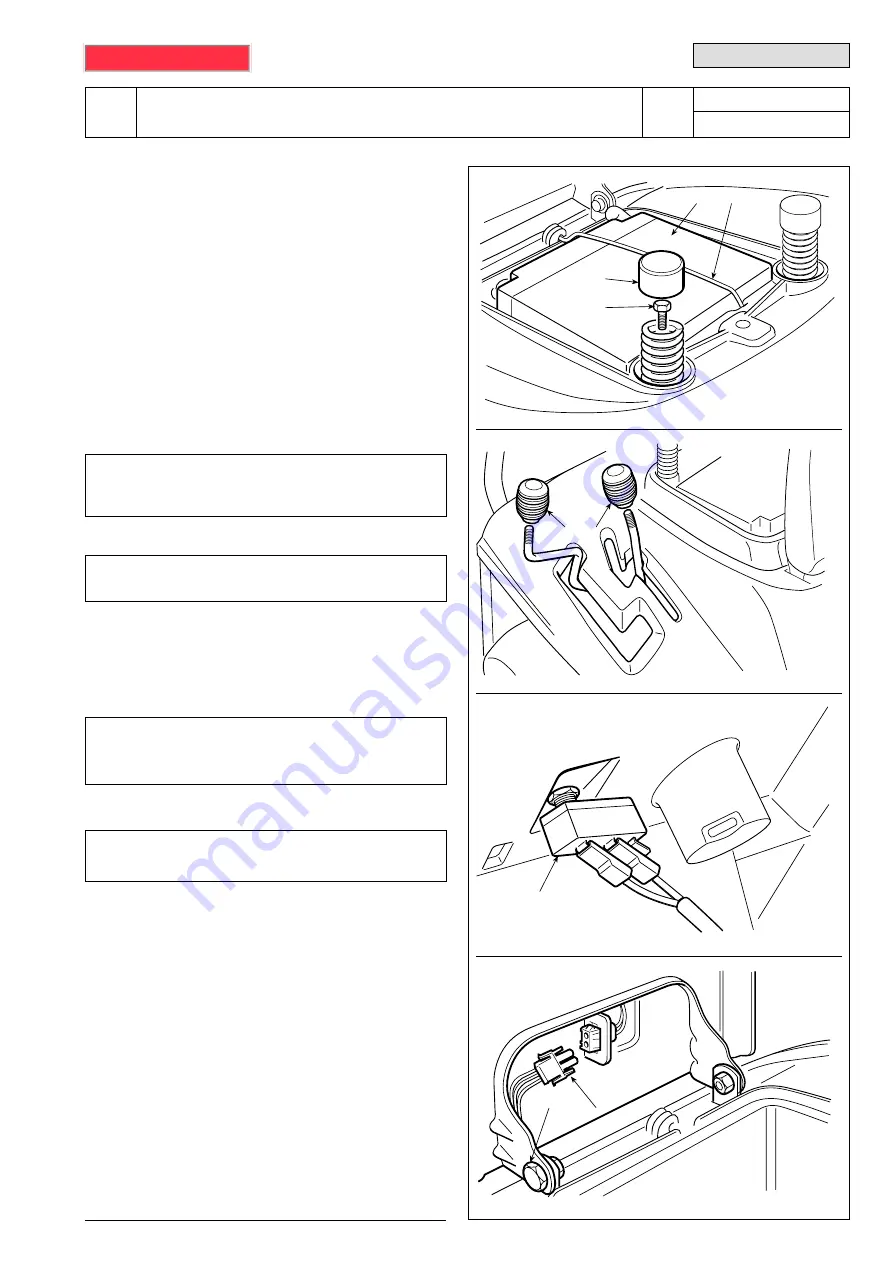
5.2 REMOVAL OF THE WHEEL COVER
Removing the wheel cover gives access to:
– the mount for the lever to raise the deck;
– the supports of the footboards.
Remove the spring
(1)
fixing the battery, ensuring that
accidental short circuits are not caused; first discon-
nect the black cables (earth), then the red cable (pos-
itive) and remove the battery
(2)
.
➤
For models with lever operated engage-
ment:
unscrew the blade engagement lever knob
(3)
➤
For mechanical drive models:
unscrew the
gear lever knob
(4)
.
Remove the caps
(5)
from the springs and undo the
screws inside
(6)
.
➤
Up to serial no. 156930,
disconnect the seat
microswitch cables
(7)
, marking them so that they
can be replaced correctly during assembly.
➤
From serial no. 156931
, disconnect the seat
operator present signal connector
(8)
.
Remove the seat after having dismantled the two pins
(9).
The cover
(10)
is fixed by two screws
(11)
located
under the side footboards and two screws
(12)
fixing
it to the rear plate.
The cover can be removed after setting the cutting
height adjustment lever to position «7» and the
engagement lever
(
➤
in models with lever operated
engagement)
to the «blades engaged» position.
8
9
3/2002
7
3
4
2
5
1
6
102 - 122
5.2
.
0
- REMOVAL OF THE WHEEL COVER
1 / 2
from
2000
to
••••
WORKSHOP MANUAL
page
<= ... RET ... <=


