RETRIEVER CITY DOG BIN INSTRUCTION LEAFLET
NOTE:
Ensure that all relevant personnel read the points listed below and that a copy is passed on to staff involved
with the installation. Please also refer to the ‘Manual Handling Operations Regulations 1992’ during the handling of the
product and materials used for installation.
TM
OPERATION:
P. 1
AND RETRIEVER ARE TRADEMARKS OF GLASDON GROUP AND ITS SUBSIDIARIES IN
THE U.K. AND OTHER COUNTRIES.
Replacement components are available direct from GLASDON.
GLASDON cannot be held responsible for claims arising from incorrect installation, unauthorised modifications or misuse of
the product.
Issue 1
September 2010
C000/0364
© Copyright 2010
Glasdon U.K. Ltd reserves the right to alter specifications without prior notice.
Glasdon U.K. Limited
Preston New Road
BLACKPOOL
Lancashire FY4 4UL
Tel: 01253 600410
Fax: 01253 792558
E-mail: [email protected]
Web: www.glasdon.com
P. 4
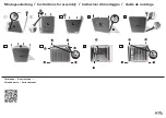
Opening and Closing:
Using the Sack Retention:
1.
Lift the sack band (Fig. C) and
drop a sack between it and the
back of the bin.
2.
Loop the sack over the two bungs
at the back of the bin and over the
sack band (Fig.D).
3.
Push the sack band down into place
to secure the sack.
4.
Reverse this process to release and
replace the sacks.
1.
Insert key in to the key hole (Fig. A) and
place left hand in the sack dispenser hole.
Turn the key anti-clockwise until it stops.
2. Using the sack dispenser as a handle lift
the door to allow it to swing open (Fig. B).
3.
To close simply slam the door shut,
ensuring the door drops into position.
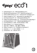
WALL MOUNTING
Fig. M
Fig. A
Fig. N
Fig.B
Fig. D
Fig. C
Kit Contents:
ITEM 1
M8 x 100mm Bolt
x 4
ITEM 2
Steel Sleeve
x 4
ITEM 3
M8 x 20mm Washer x 4
Tools Required:
M6 x 120mm Masonry Drill Bit
Hand Drill
12mm Torque wrench
1.
Drill through the 4 points in circular
recesses in the back internal wall of
the bin as shown in Fig. L.
2.
Hold the bin against the wall at the
desired height and mark the 4 off
hole positions.
3.
Drill the 4 marked holes with the
M6 Drill Bit (Fig. M).
4.
Remove any dust or debris from the
4 holes.
5.
Insert bolts (Item 1), sleeves (ITEM
2) and washers (Item 3) through the
bin and into the wall (Fig. N). Apply
pressure and screw into the wall with
a 12mm wrench. Tighten to 25Nm.
NOTE: Suitable for use in concrete, brick,
block and stone walls. Any other walls
should be individually assessed and the
appropriate fixings utilised with 20mm
diameter washers.
Fig. L