EDR User’s Manual
39
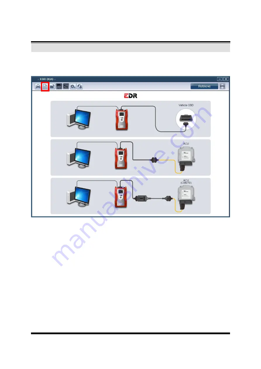
After click button as [Figure 10], Initial screen will be displayed.
[Figure 10] Initial screen
Initial screen
Page 1: ...6 General features 16 PC Interface 16 VCI Vehicle Communication Interface 17 Added Interface 17 Main Components 17 Power On off method and switch operation 18 Turning on the VCI module 18 VCI Display...
Page 2: ...d adapter 32 Enter Additional information 33 Check connector part number 34 Retrieve 35 Retrieve completed 36 PDF file save 37 Open saved file 38 Initial screen 39 Summary of each event in one page 40...
Page 3: ...EDR User s Manual 3 Read me first Introduction to EDR Safety warnings and cautions before use 1 Section 1 G e t t i n g Sta r t e d...
Page 4: ...produced in any form without the prior written permission of Global Information Technology Co Ltd No patent liability is assumed with respect to the use of the information contained herein 2012 Global...
Page 5: ...on status 2 An accurate analysis of a safety device performance Relevant laws part 563 of title 49 Code of Federal Regulations Composition of EDR EDR Event Data Recorder is composed of VCI Vehicle Com...
Page 6: ...the vehicle Avoid contact or disturbing other equipment and parts during vehicle operation Do not use another High Power electrical supply device for power input on the VCI module except the car batte...
Page 7: ...d negative Battery cables before attaching the extension cable to the power supply cable Beware of contacting any hot or moving engine parts or belts while using the extension cable and power cable wi...
Page 8: ...EDR User s Manual 8 EDR Components 1 Section 2 Components of EDR...
Page 9: ...it Windows 7 32bit 64bit CPU 2 GHz USB 1 1 Memory 1 GB RAM 1 Carrying Case G1GKNHA001 Carrying Case for keeping or moving the EDR products 1 Assy VCI module G1CHDMK050 VCI module for scan tool functio...
Page 10: ...1 AC power cable G1CDKCA001 Cable for AC DC adapter Standard format IEC 60320 C13 1 CFCI module G1DDDME001 Used to communicate with CAN FD applied vehicles 1 Adapter 36pin G1ZDDPA001 Adapter for comm...
Page 11: ...004 Adapter for communication with TF HEV QF TF vehicles Length 0 4m Color Yellow 1 Adapter 27pin 39pin G1ZDDPA006 Adapter for communication with YD vehicle Length 0 4m Color Yellow 1 Adapter 27pin 39...
Page 12: ...r for communication with KH vehicles Length 0 4m Color Yellow 1 Adapter 44pin G1ZDDPA012 Adapter for communication with PS PS EV YP YPM YD vehicles Length 0 4m Color Yellow 1 Adapter 44pin 44pin G1ZDD...
Page 13: ...on with DE HEV SC CK DE PHEV DE EV RJ BDM vehicles Length 0 4m Color Yellow 1 Adapter 44pin 44pin G1ZDDPA023 Adapter for communication with JF HEV JF PHEV vehicles Length 0 4m Color Yellow 1 Adapter 3...
Page 14: ...EDR User s Manual 14 Part name Part number Description Qty Adapter 27pin 39pin G1ZDDPA028 Adapter for communication with SP2 vehicles Length 0 4m Color Yellow 1...
Page 15: ...EDR User s Manual 15 1 Specifications and features Power On off method and switch operation Installation of VCI module and DLC main cable Section 3 B a s i c Fe a t u r e s...
Page 16: ...08MHz Memory RAM 32MByte ROM 32MByte Operating Voltage 7 35VDC Operating Temperature 14 158 10 70 USB Mode 14 131 10 55 Wireless LAN Mode Operating Mode Diagnosis Function Flight Record Function Curre...
Page 17: ...2 0B K Line L Line ISO 9141 ISO 9141 CARB KWP 2000 Commercial Veh SAE J1708 RS 232C Data Control Line Melco Pull Down UART Added Interface Item Specifications 1 VSS Vehicle speed simulation 2 Voltage...
Page 18: ...connect the main DLC cable from the vehicle to the VCI module and depress the main power switch If the vehicle DLC diagnosis connector does not use a 16 pin connector or if battery power cannot be sup...
Page 19: ...n refers to Normal diagnosis mode VEH COMM The current condition of Vehicle communication to the VCI module can be monitored using this LED This LED is Green PC COMM Displays communication mode betwee...
Page 20: ...strument panel on the driver s side DLC may be installed in the engine room Check for the proper location on each vehicle Some older model vehicles which do not use a 16 pin OBD II diagnosis SAE J1962...
Page 21: ...R User s Manual 21 WARNING When installing or disconnecting the cables always use the connector handle after confirming the connector lock tabs are released Figure 5 Correct Method of Connecting Cable...
Page 22: ...ep the VCI module as far away from clutch brake or acceleration pedals as possible Always operate the vehicle in a safe manner Be sure that the DLC main cable is connected securely Figure 2 Connecting...
Page 23: ...res require using the USB cable instead of wireless LAN while communicating between the Information Terminal and the VCI module While installing the USB cable to the VCI module the USB cable must be t...
Page 24: ...lock tabs at the Information Terminal side connector on the USB cable therefore use caution when checking the connecting condition between the USB cable and Information Terminal especially while movi...
Page 25: ...EDR User s Manual 25 Start up procedures Main screen layout Select Vehicle 1 Section 4 D e fa ul t b e havi o r...
Page 26: ...26 Start up procedures default behavior Start up procedures After software installation double click EDR shortcut icon on the desktop as shown in Figure 1 Figure 1 EDR shortcut icon displayed on the...
Page 27: ...ed of menu bar to use EDR tab menu is the row where the selection of vehicle type initial screen opening of PDF file saving of PDF file summary report setting and Internet update are available EDR pro...
Page 28: ...uto VIN search function Return to Home screen Open saved PDF file View and save EDR Report as PDF file This function summarizes and shows each event in one page Product name copyright information can...
Page 29: ...reen vehicle selection screen will be displayed When vehicle search page displayed And Vehicle can be selected in following two ways Vehicle which needs to be diagnosed can be selected in two ways 1 E...
Page 30: ...retrieved vehicle initialize the selected vehicle Manufacturer s vehicle models are displayed The adapter of the relevant vehicle is displayed Complete the Vehicles selection Clear the Vehicles select...
Page 31: ...EDR User s Manual 31 Enter 17 digits VIN chassis number and click Search button Vehicle adapter system will be displayed automatically as Figure 2 Figure 2 VIN input full VIN Choose the vehicle by VIN...
Page 32: ...ill be displayed as Figure 3 Select vehicle adapter type in order If this method used VIN search will not functioning Vehicle can be diagnose But vehicle information cannot be confirmed automatically...
Page 33: ...ual 33 When vehicle selected additional information User entered VIN User Name Case Number Crash Date Tire Size s Memo can be inserted as Figure 4 Figure 4 Enter Additional information Enter Additiona...
Page 34: ...l information please check connector part number as Figure 5 And connect VCI connector with ECU unit When communicating directly with vehicle connector part numbers are not require And it could be ign...
Page 35: ...35 When VCI and connector has connected click Retrieve button Communication indicator color will be changed to red Pop up window will be appear and retrieve will be in progress Figure 6 Retrieve in p...
Page 36: ...EDR User s Manual 36 When the scan is complete search results are expressed PDF file format as Figure 7 Figure 7 Retrievecompleted Retrieve completed...
Page 37: ...EDR User s Manual 37 When the scan is complete click the Save button as Figure 8 to save PDF file Figure 8 PDF file save PDF file save...
Page 38: ...EDR User s Manual 38 After click button as Figure 9 saved PDF file can be open Figure 9 Saved file open Open saved file...
Page 39: ...EDR User s Manual 39 After click button as Figure 10 Initial screen will be displayed Figure 10 Initial screen Initial screen...
Page 40: ...items may vary according to the vehicle type and the summary items will not be displayed if there is no event The summary items including vehicle speed engine throttle operation of brake pedal engine...
Page 41: ...EDR User s Manual 41...
Page 42: ...EDR User s Manual 42 Figure 12 Summary items for each event...
Page 43: ...EDR User s Manual 43 The user guide manual and language change are the functions shown when the setting button is clicked as shown in Figure 13 Figure 13 Configuration Configuration...
Page 44: ...EDR User s Manual 44 This function can update software and VCI firmware when the Internet update button is clicked as shown in Figure 14 Figure 14 Internet Update Internet Update...
Page 45: ...EDR User s Manual 45 Disposal of old electrical and electronic equipment 1 Section 5 A p p e n d i x...
Page 46: ...Applicable in the European Union and other European countries with separate collection systems This symbol on the product or on its packaging indicates that this product shall not be treated as house...