


Handling instructions
for GISMA connectors
HI
– 2007 - 001
Document: replaces
MV 2000-020,
MV 2000-030 and
MV 2005 - 011
First issue:
15.07.2008
Rev.-Index: -Z-
From:
29.07.2020
Copyright by:
GISMA GmbH
Page 40 of 44
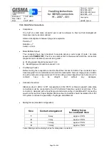
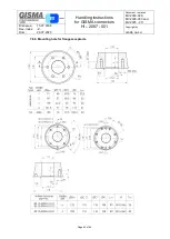
7.8.6. Stab Plate Connectors
Compliance
One half of a stab mate connector pair must be allowed to float so that misalignment
tolerances can be accommodated.
Allowed misalignment between plug and receptacle:
Pan/tilt: ±1°
Rotation:
±1°
Radial: ±0,5mm
Mate/DeMate Speed
The connectors have been designed to operate across a wide range of mate / de-mate
speeds with
POWER OFF
. There is no practical limit to the speed at which the connectors
maybe mated or demated, however as a guide: -
a) Mating speed should not exceed 1 m/s.
b) Demating speed should not exceed 1 m/s.
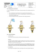
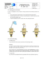
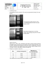
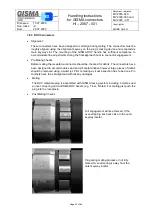
Pre-Mating Checks
Before mating, the receptacle connector should be checked for debris. The connectors have
been designed to accommodate sand and silt contamination however large pieces of debris
should be removed using a water jet. Prior to mating a visual inspection has to be done. Pin
contacts
have
to
be
straight
and
without
any
damages.
Cathodic Protection:
Stainless steel (1.4404/ 1.4571 comparable to 316L/316Ti) or titanium grade 5 stab plate
connectors must be connected to the CP (Cathodic Protection) system at all times. If the
connector is designed with a fixed flange and screw mounting, an additional CP connecting
would not be required. Super Duplex stainless steel connectors should be isolated from the
CP system to reduce the possibility of hydrogen embrittlement.
Mating forces (standard configuration)
Size
Contact arrangement
Mating forces
for contact-Ø 3mm
1
4-way
approx. 200 N
2
7-way
approx. 350 N
3
12-way
approx. 550 N
4
19-way
approx. 750 N
Table: Mating and de-mating forces for stab plate connectors


