background image


FlexPay NC3L Wide Installation and maintenance


iii 

NOTES 


This equipment complies with the following EU applicable for the purpose of CE marking 

Low Voltage Directive    

                                                                      2014/35/EU 

Electromagnetic Compatibility Directive                                                           2014/30/EU 

RoHS Directive (Restriction of Hazardous Subastances Directive)                 2011/65/EU 
 
Radio Equipment directive                                                                               2014/53/EU 
 
and thus features the CE marking. 
 
This equipment also complies with the applicable requirements of the Measuring Instruments Directive, 
2004/22/EC until 04/19/2016 and 2014/32/EU from 04/20/2016, according to the Evaluation Certificate. 

Note 

This equipment is generally used in Petrol Stations, so it has been evaluated together the dispenser whose it 
is a part and it is suitable to be used when properly installed and maintained following the provisions of this 
manual. 
 
Please observe that the pictures in this manual show a general version of crind and fuel dispenser.  
Details in the delivered model may differ.

Summary of Contents for FlexPay NC3L Wide

Page 1: ...FlexPay NC3L Wide 71A8463279GB E03 01 09 2018...

Page 2: ...s or arising from installation repair maintenance by anyone other than authorized personnel or from usage of non original spare parts improper maintenance or alteration accident misuse abuse and negle...

Page 3: ...his equipment also complies with the applicable requirements of the Measuring Instruments Directive 2004 22 EC until 04 19 2016 and 2014 32 EU from 04 20 2016 according to the Evaluation Certificate N...

Page 4: ...LAIMER The equipment installed and put into service following the instructions given in this manual will operate fully covering the characteristics described here Installation and put into service of...

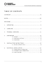
Page 5: ...7 1 DEFINITION 8 2 LABELLING 9 3 TERMINAL OVERVIEW 11 4 DIMENSIONS 13 4 1 WEIGHT 13 4 2 UNPACKING THE NC3L 14 4 3 PLACEMENT 14 5 INSTALLATION INSTRUCTIONS 15 5 1 INSTALLATION OF NC3L 16 6 ELECTRICAL I...

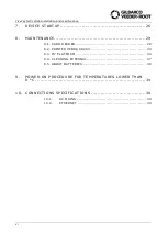
Page 6: ...ARTUP 26 8 MAINTENANCE 29 8 1 CARD READER 29 8 2 PRINTER ZEBRA KR203 30 8 3 M7 PLATFORM 34 8 4 CLEANING EXTERNAL 37 8 5 ABOUT BATTERIES 38 9 POWER ON PROCEDURE FOR TEMPERATURES LOWER THAN 0 C 39 10 CO...

Page 7: ...ame inside texts updated Changes brought to the previous edition 01 dated 12 02 2018 First Official Manual Release Terminal overview updated Product name changed and text updated Device power on chapt...

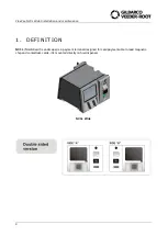
Page 8: ...nstallation and maintenance 8 1 DEFINITION NC3L NordicCard 3 Landscape is a payment terminal designed for card payment able to read magnetic chip and contactless cards it is mounted directly on fuel d...

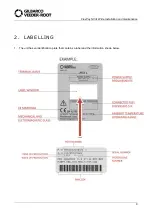
Page 9: ...FlexPay NC3L Wide Installation and maintenance 9 2 LABELLING 1 The unit has an identification plate that contains a label and the information shown below...

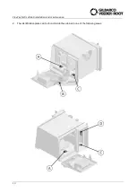
Page 10: ...FlexPay NC3L Wide Installation and maintenance 10 2 The identification plate can be found inside the cabinet in one of the following areas...

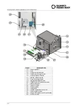
Page 11: ...and maintenance 11 3 TERMINAL OVERVIEW PART DESCRIPTION 1 LCD 12 display 3 Key Lock 4 Card rearder Printer door 5 Contactless antenna 6 Card reader inlet 7 Pin pad 8 Cable channel 9 Cabinet 10 Displa...

Page 12: ...pass through cover 16 Audio amplifier module 17 M7PS M7IF boards 18 Touch interface board 19 Display Backlight module 20 TBSP power connection module 21 Ethernet Switch 22 Heater module 23 Power supp...

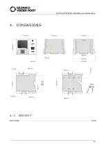
Page 13: ...FlexPay NC3L Wide Installation and maintenance 13 4 DIMENSIONS 4 1 WEIGHT NC3L Wide 50 kg...

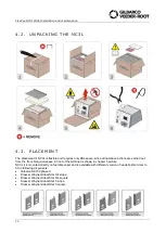
Page 14: ...ut from the front Required space in front of the terminal is shown in chapter 3 picture NC3L it is mounted directly on fuel dispenser and is available with different version of reader printer door to...

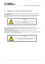
Page 15: ...in place Disconnect all supply lines before starting the installation Terminals do not have a safety switch but such shall be installed in the electrical power centre The terminal shall not be modifi...

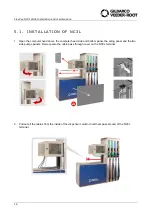
Page 16: ...he computer head doors the computer head side and bottom panel the airing panel and the two side pumps panels Remove also the cable pass through cover on the NC3L terminal 2 Pull out all the cables fr...

Page 17: ...tenance 17 3 Mount the small size airing panel fastening the screws 4 Fasten for half length the four M6 screws on the dispenser computer head thread If there is not any fixing thread available fasten...

Page 18: ...gh centre of gravity Some lifts may require two persons 5 Insert the four screws head in the keyhole shaped holes of NC3L terminal pushing it upward 1 and then moving it toward the column 2 6 Open the...

Page 19: ...of crushing pinch hazard Open the doors gently Avoid placing fingers or hands between the doors when they are moving 7 Open the pinpad display unit s doors turning the key situated inside the reader p...

Page 20: ...that the terminal is lined up with the computer head then tighten up the four screws inside the NC3L terminal 9 For each terminal side follow this sequence Insert additional two M6 screws with grower...

Page 21: ...hat also supply lines are isolated from mains by safety disconnection devices WARNING This device must be installed into an electrical system complying with the plant engineering regulations in force...

Page 22: ...any daily downtime Failure to comply with the above provision may cause damages to some system components See DISCLAIMER page WARNING The electrical cables used for connections must comply with the p...

Page 23: ...following the relevant diagram 6 2 ETHERNET CABLE CONNECTION 1 For Ethernet connection cable features see paragraph Ethernet connection 2 Connect the Ethernet cable from the Ethernet switch situated...

Page 24: ...with four M6 flange nuts 2 Make sure that all the external cables are correctly passed and check against sharply bent cables Bending the cable too sharply or repeatedly may cause damage to the wires...

Page 25: ...the self adhesive gaskets on four corners as shown in picture Remove the protection film from the weather cover and apply it to the lower part of the pump electronic head Note that these parts are av...

Page 26: ...er than 0 C chapter before terminal switching on 2 Turn on the switch located behind the reader printer door on both sides Danger Take care turning off the switches will shut down devices but supply l...

Page 27: ...o Printer owner manual into receipt printer 4 To close correctly the display unit s door pull the lever using a long screwdriver as show in the image keep the lever pulled for next step 5 Close the di...

Page 28: ...FlexPay NC3L Wide Installation and maintenance 28 6 Close and lock the reader printer unit s doors parts 4 turning the keys parts 3 90 counter clockwise and closing the keyhole covers...

Page 29: ...ndicates that the safety processor is transmitting data to the card reader module inside the device Off On The safety processor is not transmitting data on the port 4 C Reader Rx Green Blinking It ind...

Page 30: ...print head will print a self test printout Press and hold Feed while turning on the printer or press and hold Feed just after closing the print head to print a self test printout Press and hold Feed w...

Page 31: ...m paper cannot be ejected retracted 2 Cutter cannot return to home position 3 Out of paper 4 Print Head lifted 5 Paper feed error under head 6 Temp error print head is above 60 C 7 Paper jam during pr...

Page 32: ...aper Jams Should a paper jam occur follow the procedure below 1 Open the print head by pressing the green release lever toward the rear of the printer 2 Lift the print head 3 Remove all jammed paper a...

Page 33: ...ed ON 4 Cut the paper at a suitable angle 90 ATTENTION The paper sensor for 58 mm and 60 mm paper is at the same side as the interface connector while the sensor for 80 mm and 82 5 mm paper is on the...

Page 34: ...The table below describes the LEDs N LED COLOUR STATUS DESCRIPTION 1 5 V Green On The voltage is present Off The voltage isn t present 2 12 V Green On The voltage is present Off The voltage isn t pre...

Page 35: ...On No device attached Green Device attached 16 MICRO_STAT Red On No device attached Green Device attached 17 USB_Q_UART_PORT Red On USB to quad UART port is disabled 18 MICRO_PORT Red On Microcontrol...

Page 36: ...R STATUS DESCRIPTION 1 ETH Orange On Net connected Off Net disconnected Off On Communication isn t present 2 Status LED Green Blinking slow Display is connected to UPM and the unit is activated Blinki...

Page 37: ...nce a year to keep them glossy and resistant to pollution If the payment terminal is equipped with a touch screen it is important that water or snow doesn t form a connection between the glass and the...

Page 38: ...sed only by trained personnel certificated by Gilbarco WARNING Failure to comply with the above provision may cause damages to components or their functionality See DISCLAIMER at page iv Disposal of t...

Page 39: ...hours until manual heating procedure will be completed 6 Open the NC3L printer and reader doors and switch on power button 7 Close the NC3L doors 10 CONNECTIONS SPECIFICATIONS 10 1 AC MAINS Power sup...

Page 40: ...FlexPay NC3L Wide Installation and maintenance 40...

Page 41: ...2018 Gilbarco Italia S r l Via de Cattani 220 G 50145 Firenze Italia Tel 39 055 30941 Fax 39 055 318603 http www gilbarco it...

Reviews: