Page 5-5
External Flow Meter Calibration
VaporTEK Calibration Start-up Sequence
MDE-5394B VaporTEK™/VaporTEK-3 Controller Board 110 V UL® Vapor Recovery Collection System for Encore® 500 S
Start-Up and Service Manual · March 2019
1
Verify that the power is available at the VaporTEK-3 Controller by confirming LED V1 and
V6 (red) are on and LED V3 (green) is flashing.
2
Connect the FB1 terminal to RS-422 connector on the VaporTEK-3 Controller
(see
3
Connect the gas meter encoder cable to FB1 terminal.
4
Connect the hoses to gas meter.
5
Ensure that the nozzle is shut off (vapor valve closed) to perform the leak test.
The following table lists the FB1 terminal key descriptions
:
External Flow Meter Calibration
External flow meter calibration must be completed before conducting a system calibration. To
calibrate the external flow meter, proceed as follows:
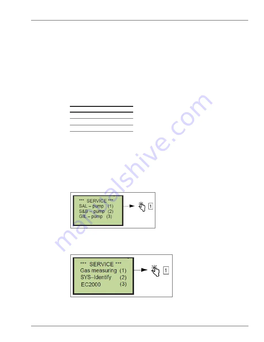
1
Press the
Start
button until the following screen opens, and then press
1
.
Figure 5-2: Gas Meter Calibration - Screen 1
2
Press
1
when the following screen opens.
Figure 5-3: Gas Meter Calibration - Screen 2
Key
Description
START
Power ON the FB1 Terminal
ENTER
Confirm Selection
SHIFT
Cancel Selection


