


GD32E23x User Manual
361
cannot be set both to active level when break occurs. The break sources are input break pin
and HXTAL stuck event by Clock Monitor (CKM) in RCU. The break function enabled by
setting the BRKEN bit in the TIMERx_CCHP register. The break input polarity is setting by
the BRKP bit in TIMERx_CCHP.
When a break occurs, the POEN bit is cleared asynchronously, the output CHx_O and
CHx_ON are driven with the level programmed in the ISOx bit and ISOxN in the
TIMERx_CTL1 register as soon as POEN is 0. If IOS is 0 then the timer releases the enable
output else the enable output remains high. The complementary outputs are first put in reset
state, and then the dead-time generator is reactivated in order to drive the outputs with the
level programmed in the ISOx and ISOxN bits after a dead-time.
When a break occurs, the BRKIF bit in the TIMERx_INTF register is set. If BRKIE is 1, an
interrupt generated.
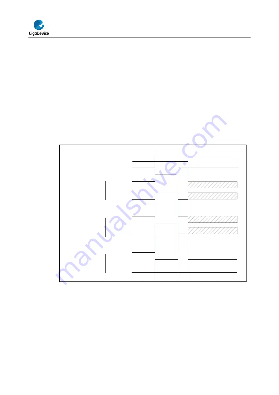
Figure 14-65. Output behavior in response to a break(The break high active)
OxCPRE
CHx_O
CHx_ON
BRKIN
CHx_O
CHx_ON
CHx_O
CHx_ON
= ISOx
= ISOxN
= ISOx
= ISOxN
CHxEN: 1 CHxNEN: 1
CHxP : 0 CHxNP : 0
ISOx = ~ISOxN
CHxEN: 1 CHxNEN: 0
CHxP: 0 CHxNP : 0
ISOx = ~ISOxN
CHxEN: 1 CHxNEN: 0
CHxP : 0 CHxNP : 0
ISOx = ISOxN
Master-slave management
The TIMERx can be synchronized with a trigger in several modes including the restart mode,
the pause mode and the event mode which is selected by the SMC[2:0] in the
TIMERx_SMCFG register. The trigger input of these modes can be selected by the
TRGS[2:0] in the TIMERx_SMCFG register.


