


System Appearance
- 18 -
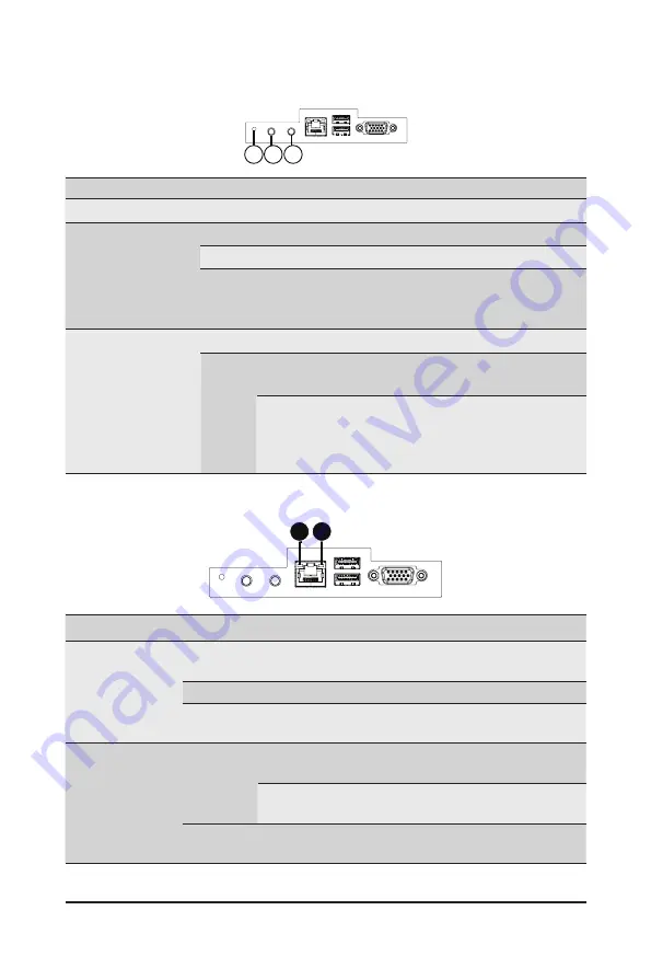
2-6 Rear System LEDs and Buttons
No.
Name
Color
Status
Description
1.
ID Button
Press the button to activate system identification
2.
Power button
with LED
Green
On
Indicates the system is powered on.
Green
Blink
System is in ACPI S1 state (sleep mode).
N/A
Off
• System is not powered on or in ACPI S5 state
(power off)
• System is in ACPI S4 state (hibernate mode)
3.
System
Status LED
Green
Solid On System is operating normally.
Red
Solid On
Critical condition, may indicate:
System fan failure; System temperature
Blink
Non-critical condition, may indicate:
Redundant power module failure
Temperature and voltage issue
Chassis intrusion
1
3 2
1 2
No.
Name
Color
Status
Description
1.
1GbE
Speed LED
Yellow
On
1 Gbps data rate
Green
On
100 Mbps data rate
N/A
Off
10 Mbps data rate
2.
1GbE
Link/
Activity
LED
Green
On
Link between system and
network or no access
Blink
Data transmission or receiving is occurring
N/A
Off
No data transmission or
receiving is occurring
Summary of Contents for S252-ZC0
Page 1: ...S252 ZC0 2U 24 2 Bay DP Storage Server AMD MILAN ROME User Manual Rev 1 0...
Page 13: ...13 Hardware Installation 1 3 System Block Diagram...
Page 37: ...37 System Hardware Installation HDD Backplane Board Signal Cable PMBus Signal Cable...
Page 38: ...System Hardware Installation 38 HDD Backplane Board Power Cable 1 2 ATX Power Cable...
Page 39: ...39 System Hardware Installation GPU Power Cable 0 1 Fan Power Cable...
Page 41: ...41 System Hardware Installation SlimLine to NVMe Cable 0 1 P0 U 2 0 P1 U 2 1...
Page 52: ...BIOS Setup 52 When Boot Mode Select is set to Legacy in the Boot Boot Mode Select section...
Page 57: ...57 BIOS Setup 5 2 4 1 Serial Port 1 2 Configuration...
Page 65: ...65 BIOS Setup 5 2 8 PCI Subsystem Settings...