


System Hardware Installation
- 36 -
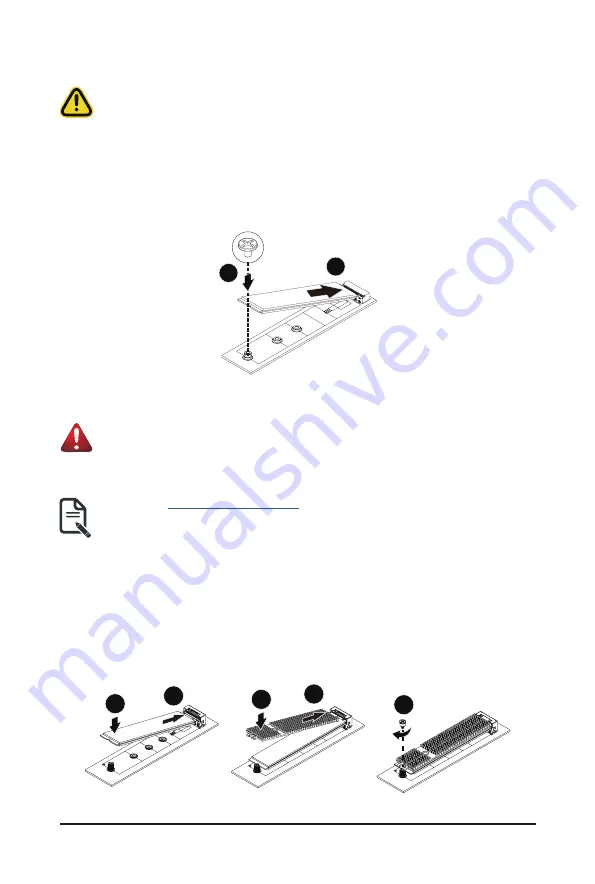
3-9 Installing the M.2 Device and Heat Sink
CAUTION
The position of the stand-off screw will depend on the size of the M.2 device. The stand-off screw
is pre-installed for 22110 cards as standard. Refer to the size of the M.2 device and change the
position of the stand-off screw accordingly.
Follow these instructions to install the M.2 device:
1. Insert the M.2 SSD module into the slot.
2. Secure it with the screw, tightening as necessary to fasten the M.2 SSD module in place.
1
2
3-9-1 M.2 device with Heatsink
WARNING:
Please ensure a heatsink is attached to any M.2 device installed into the system. Installing an M.2
device without any heatsink may result in the system overheating or system performance being
throttled.
• Please Go to
for specific M.2 Slot location.
• To install/remove the M.2 module and Heatsink use a No. 1 Phillips-head screwdriver with a screw
torque of 1.5 ± 0.2 kgf*cm
Follow these instructions to install the M.2 device and heat sink:
1. Insert the M.2 device into the M.2 connector.
2. Press down on the M.2 device.
3. Install the thermal pad of the M.2 device to the M.2 device.
4. Press down on the thermal pad.
5. Secure the M.2 device and its thermal pad to the motherboard with a single screw.
6. Reverse steps 1-2 to remove the M.2 device.
2
4
1
3
5
Summary of Contents for R183-Z91
Page 13: ...Hardware Installation 13 1 3 System Block Diagram ...
Page 42: ...System Hardware Installation 42 CPU1 CPU0 A A B A A C D D D D D E B B C C D E E A ...
Page 59: ...BIOS Setup 59 When Boot Mode Select is set to Legacy in the Boot Boot Mode Select section ...
Page 71: ...BIOS Setup 71 5 2 8 PCI Subsystem Settings ...
Page 83: ...BIOS Setup 83 5 2 18 Intel R I350 Gigabit Network Connection ...
Page 89: ...BIOS Setup 89 5 3 1 CPU Common Options ...
Page 121: ...BIOS Setup 121 5 3 4 NBIO Common Options ...