


- 17 -
System Appearance
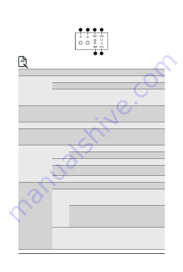
2-3 Front Panel LED and Buttons
1
2
3
5
4
6
• Systems equipped with RoT have different Status LED and ID LED indicators.
See
2-3-1 RoT LEDs
to check status.
No. Name
Color
Status
Description
1.
Power button
with LED
Green
On
System is powered on
Green
Blink
System is in ACPI S1 state (sleep mode)
N/A
Off
•
System is not powered on or in ACPI S5 state
(power off)
•
System is in ACPI S4 state (hibernate mode)
2.
ID Button
N/A
Off
•
System is not powered on or in ACPI S5 state
(power off)
•
System is in ACPI S4 state (hibernate mode)
3.
Reset Button
Press the button to reset the system.
4.
NMI button
Press the button server generates a NMI to the processor
if the multiple-bit ECC errors occur, which effectively halt
the server.
5.
HDD Status
LED
Green
On
HDD locate
Blink
HDD access
Amber
On
HDD fault
Green/
Amber
Blink
HDD rebuilding
N/A
Off
No HDD access or no HDD fault.
6.
System
Status LED
Green
Solid On System is operating normally.
Amber
Solid On
Critical condition, may indicate:
System fan failure
System temperature
Blink
Non-critical condition, may indicate:
Redundant power module failure
Temperature and voltage issue
Chassis intrusion
N/A
Off
System is not ready, may indicate:
POST error
NMI error
Processor or terminator missing
Summary of Contents for G492-Z52
Page 1: ...G492 Z52 HPC Server 4U DP 10 x Gen4 GPU Server Broadcom solution User Manual Rev 1 0 ...
Page 28: ... 28 System Hardware Installation 3 5 4 6 6 6 ...
Page 30: ... 30 System Hardware Installation 3 5 4 ...
Page 64: ... 64 BIOS Setup 5 2 7 PCI Subsystem Settings ...
Page 75: ... 75 BIOS Setup 5 2 16 Intel R i350 Ethernet Controller ...