

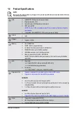

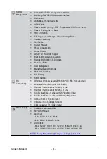
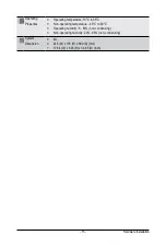


System Appearance
- 20 -
2-3 Front Panel Buttons and LEDs
1
3
4
5
6
2
No. Name
Color
Status
Description
1.
Reset Button
--
--
Press this button to reset the system.
2.
HDD Status
LED
Green
On
Indicates locating the HDD.
Blink
Indicates accessing the HDD.
Amber
On
Indicates HDD error.
Green /
Amber
Blink
Indicates HDD rebuilding.
N/A
Off
Indicates no HDD access or no HDD error.
3.
System
Status LED
Green
Solid On Indicates system is operating normally.
Amber
Solid On
Indicates a critical condition, may include:
- System fan failure
- System temperature
Blink
Indicates non-critical condition, may include:
- Redundant power module failure
- Temperature and voltage issue
- Chassis intrusion
N/A
Off
Indicates system is not ready, may include:
- POST error
- NMI error
- Processor or terminator is missing
4.
NMI Button
--
--
Press this button for the server to generate a NMI to the
processor. If multiple-bit ECC errors occur, the server will
effectively be handled.
5.
ID Button
with LED
--
--
Press this button to activate system identification.
6.
Power Button
with LED
Green
On
Indicates the system is powered on.
Green
Blink
System is in ACPI S1 slate (sleep mode).
N/A
Off
Indicates system is not powered on or in ACPI S5 slate
(power off) or system is in ACPI S4 slate (hibernation mode).
Summary of Contents for G482-Z50
Page 1: ...G482 Z50 G482 Z51 AMD EPYCTM 7002 Series Processor Server User Manual Rev 1 0 ...
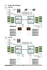
Page 16: ...Hardware Installation 16 1 3 System Block Diagram 1 3 1 G482 Z50 1 3 2 G482 Z51 ...
Page 30: ...System Hardware Installation 30 3 4 5 ...
Page 31: ... 31 System Hardware Installation 6 6 6 ...
Page 33: ... 33 System Hardware Installation 3 5 4 ...
Page 35: ... 35 System Hardware Installation 2 3 ...
Page 48: ...System Hardware Installation 48 4 ...
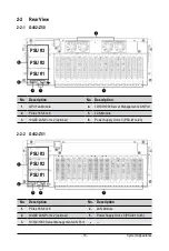
Page 54: ...System Hardware Installation 54 G482 Z51 1 2 3 2 1 3 Motherboard to 2 5 HDD Backplane Board ...
Page 80: ...BIOS Setup 80 5 2 13 SATA Configuration ...
Page 85: ... 85 BIOS Setup 5 2 18 Intel R I350 Gigabit Network Connection ...
Page 87: ... 87 BIOS Setup 5 2 19 VLAN Configuration ...
Page 91: ... 91 BIOS Setup 5 2 22 Intel R Ethernet Controller X550 ...