


- 14 -
System Appearance
Chapter 2 System Appearance
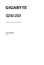
2-1 Front View
• Please Go to Chapter
2-3 Front Panel LED and Buttons
for detail description of function LEDs.
3
1
2
11
4 5 6 7 8 9 10
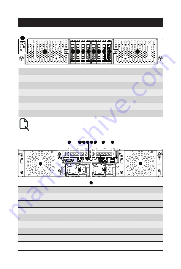
2-2 Rear View
No. Description
No. Description
1.
System Fan (GPU_FAN12E)
8.
10GbE LAN Port x 2
2.
VGA Port
9.
USB 3.0 Port x 2
3.
10/100/1000 Server Management LAN Port
10.
System Fan (GPU_FAN56E)
4.
Power Button with LED
11.
Power Supply (PSU2)
5.
ID Button
12.
NMI Button
6.
Reset Button
13.
Power Supply (PSU1)
7.
System Status LED
4
3
2
5 6 7
8
9
13
1
10
12
11
No. Description
No. Description
1.
Front Panel LED and Buttons
7.
2.5-inch Hard Disk Drive #4
2.
System Fan (GPU_FAN78)
8.
2.5-inch Hard Disk Drive #5
3.
2.5-inch Hard Disk Drive #0
9.
2.5-inch Hard Disk Drive #6
4.
2.5-inch Hard Disk Drive #1
10.
2.5-inch Hard Disk Drive #7
5.
2.5-inch Hard Disk Drive #2
11.
System Fan (GPU_FAN34)
6.
2.5-inch Hard Disk Drive #3
NOTE! Green HDD Latch Supports NVMe
Summary of Contents for G292-2G0
Page 1: ...G292 2G0 HPC Server Intel DP 2U 16 x GPU Server User Manual Rev 1 0 ...
Page 29: ... 29 System Hardware Installation 4 3 ...
Page 31: ... 31 System Hardware Installation For GPU0 GPU1 GPU2 GPU3 1 2 2 1 3 4 ...
Page 33: ... 33 System Hardware Installation 3 4 5 6 6 ...
Page 35: ... 35 System Hardware Installation 5 6 ...
Page 43: ... 43 System Hardware Installation CPU Power Cable 1 x 3 Power Cable ...
Page 44: ... 44 System Hardware Installation SMD Cable System Fan Power Cable ...
Page 47: ... 47 System Hardware Installation SlimLine SAS to SATA 2 Cable NVMe 0 1 Cable NVME 1 NVME 0 ...
Page 48: ... 48 System Hardware Installation NVMe 2 3 Cable NVME 3 NVME 2 Front Panel IO Cable ...
Page 73: ... 73 BIOS Setup 5 2 12 Intel R X710 Ethernet Network Connection ...
Page 78: ... 78 BIOS Setup 5 3 1 Processor Configuration ...