English
8
PROFESSIONAL AUTOMATIC SYSTEM FOR GATES AND GARAGE DOORS
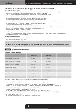
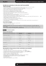
Before star ting installation, carefully read through these installation instructions exactly in the order described.
Ensure that the door structure is in a good state and suitable for motorization.
Before any installation or maintenance operation, check that the power supply has been disconnected.
Check the power supply voltage, the frequency and the safety switch.
Work away from rain, snow, humidity and combustible materials.
Do not work on a moving garage door or on moving components.
Check that the door moves smoothly and is not subject to points of friction.
Ensure that the door is well-balanced. If necessar y, adjust the balancing mechanisms.
Keep children away from the door.
Have the electrical connection and installation carried out by exper t and skilled personnel.
Only use original Gi.Bi.Di spare par ts and accessories.
Be extremely careful when fixing the par ts, since high forces come into play.
Arrange a 230V outlet near or in proximity of the planned position of the operator with a mains power cut-of f device with an op
ening
distance between the contacts of at least 3 mm.
Improper installation will lead to for feiture of the guarantee.
If necessar y, protect the pinion, chain transmission and sliding area.
Install the unit in an area not accessible to persons.
Should the power cable be damaged, it must be replaced with a cable or special assembly available at the manufacturer or
his technical ser vice.
Accessories available:
Installation instructions for the Drive Unit Version 600N
General warnings:
•
•
•
•
•
•
•
•
•
•
•
•
•
•
•
•
•
•
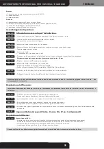
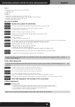
Sectional and spring-loaded doors: no accessories required.
Overhead doors: cur ved arm required.
•
•
Characteristics of the electronic control units AS01970 and AS01980:
Power supply 230VAC - 50/60Hz.
Fuse protection against shor t-circuits of the main power supply line
(F2 = F 1A)
.
Fuse protection against sho
rt-circuits of the low-voltage power supply line
(F1 = F 630mA
)
.
Possibility of control through one Open-Stop-close button or through radio control, only for AS02180.
Amperometric sensor anti-crushing device with adjustable threshold.
Provision for connection of photocells (24VDC - 5W).
Output for connection of a flashlight (24VAC 15W max.).
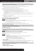
Cour tesy light on the operator (230VAC 40W max. (E14) protected by fuse (F3 = 500mA).
The courtesy lamp may be replaced only when the power is off (230 VAC).
Input for STOP button.
Card power supply Led - DL1.
Radio-control code storage Led, only for AS02180.
•
•
•
•
•
•
•
•
•
•
•
•
Accessory packs
Photo 01
General characteristics
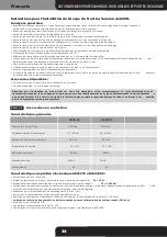
Power supply voltage
230 VAC
230 VAC
GECO 60
GECO 80
Power supply voltage frequency
50 - 60 Hz
50 - 60 Hz
Maximum power absorbed
250 W
250 W
Operating temperature
-10 / +55
-10 / +55
Max. thr ust
600 N
800 N
Nominal thrust
200 N
200 N
Cycles/hour
20
20
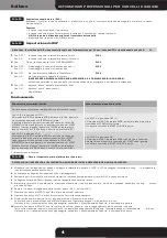
Warning: For installation of the curved arm on the overhead door, strictly follow the instructions in the leaflet supplied with
the accessory.
Bear in mind that for good functioning of this type of automation, the overhead door must not be opened completely in order to
make reclosing as easy as possible and prevent any system overloads.
Summary of Contents for GECO LUX GECO60
Page 23: ...Dis 17 F1 630mA ...
Page 24: ...Foto 01 10 13 Ø4 Ø8 Foto 02 Foto 03 Foto 04 Foto 05 Foto 06 Foto 07 ...
Page 25: ...Foto 08 Foto 09 Foto 10 Foto 11 Foto 12 Foto 13 Foto 14 Foto 15 ...
Page 26: ...Foto 16 Foto 18 Foto 19 Foto 20 Foto 21 Foto 22 Foto 23 OUT 1 OUT 2 LED ROSSO START LEARN ...


