background image

12

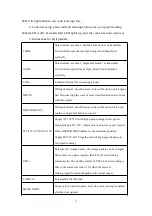
INFRARED

Terminal for photocells, active low, when the obstacle sensed by

photocell while the door is closing, the door will stop and then

rebound to open.

COM

Common terminal for connecting ground

VCC

12-28V output voltage; supply the power for photocells or other

saftey devices; current

200mA.

6. Motor running speed: Soft start when open and close the door, 700ms later

then switch to high-speed running. (Time adjusting: 0~33 seconds high speed time

can be adjusted by HSPEED TIME trimmer). When high-speed running time ends, it

switches into low-speed running till the motor stops running. When the motor stops in

the halfway for the first time during it runs from open limit position or close limit

position, then high-speed running time will adjust automatically based on previous

running time.

7. High-speed running time adjustment: Adjusting 0~30s high speed running

time through HSPEED TIME trimmer. When the trimmer turns to the minimum, it’s

0s, the high-speed running disabled, the motor keeps running in low-speed. Only

when both motors working, then high-speed running timing enabled.

8. Limit & obstacle sensitivity adjustment: During the opening and closing, the

motor stops running once the limit & obstacle sensitivity signals sensed. Sensitivity of

the two motors are set seperately. Adjusting the sensitivity of motor1 through

MOTOR1 trimmer, while MOTOR2 trimmer control sensitivity of motor2. Notice:

Arm-type motors only have the funcion of obstacle sensitivity, no functions of limit.

9. MOTOR1&2 opening/closing delay time adjustment: When opening the door,

motor2 opens first then motor1 opens later; while closing the door, motor1 closes first

then motor2 closes. And opening/closing delay time can be adjusted 0~30s.

10. Auto closing time adjustment: Auto closing funtion enabled when opening

the door by swiping the card which should have card-reader installed. Auto closing

time can be set for 0 second,5seconds and 10 seconds by using jumper. The auto

Summary of Contents for JJ-PKM-C01

Page 1: ...01 JJ PKM C01 JJ PKM C01 JJ PKM C01 USER USER USER USER MANUAL MANUAL MANUAL MANUAL TEL TEL TEL TEL NO 86 595 22499516 NO 86 595 22499516 NO 86 595 22499516 NO 86 595 22499516 FAX FAX FAX FAX NO 86 595 22492516 NO 86 595 22492516 NO 86 595 22492516 NO 86 595 22492516 WEBSITE WEBSITE WEBSITE WEBSITE www giantautogate com www giantautogate com www giantautogate com www giantautogate com ...

Page 2: ...damaged damaged damaged damaged or or or or broken broken broken broken it it it it must must must must be be be be replaced replaced replaced replaced by by by by the the the the manufacturer manufacturer manufacturer manufacturer its its its its service service service service agent agent agent agent or or or or qualified qualified qualified qualified persons persons persons persons in in in in ...

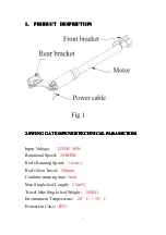
Page 3: ... OPENER OPENER OPENER TECHNICAL TECHNICAL TECHNICAL TECHNICAL PARAMETERS PARAMETERS PARAMETERS PARAMETERS Input Voltage 24VDC 40W Rotational Speed 250RPM Rod s Running Speed 1 6cm s Rod s Max Travel 300mm Continue running time 5min Max Single leaf Length 2 5m 2 Travel Max Single leaf Weight 200KG Environment Temperature 20 C 50 C Protection Calss IP55 ...

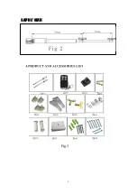
Page 4: ...4 3 SPEC 3 SPEC 3 SPEC 3 SPEC SIZE SIZE SIZE SIZE Fig 3 ...

Page 5: ...5 5 INSTALLATION 5 INSTALLATION 5 INSTALLATION 5 INSTALLATION DESCRIPTION DESCRIPTION DESCRIPTION DESCRIPTION 5 1 Required tools for installation Fig 4 5 2 Installation diagram Fig 5 Fig 6 ...

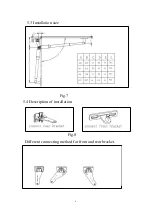
Page 6: ...6 5 3 Installation size Fig 7 5 4 Description of installation Fig 8 Different connecting method for front and rear bracket ...

Page 7: ... installation method according to different material and environment for front bracket Connection for rear bracket and motor The height difference for installing the front and rear bracket Installation for front bracket ...

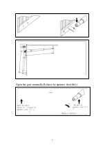
Page 8: ...8 Open the gate manually Release by spanner then lift it ...

Page 9: ...ol Control Control Panel Panel Panel Panel 1 1 1 1 Technical Technical Technical Technical Parameters Parameters Parameters Parameters 1 Control Panel Voltage Input 220VAC 2 Motor s Voltage 12VDC 24VDC 3 Encoder For transmitter Our own customed rolling code 4 Support remote control Can memorize 20PCS transmitters at most 5 Range of application Suit for all double arms swing gate opener ...

Page 10: ...ng code state or removing code state it flashes twice after successfully learning code or removing code 2 Transmitter using our company own customed rolling code Singe leaf button controls opening and closing of MOTOR2 double leaf button simultaneously controls opening and closing of MOTOR1 MOTOR2 The control panel can memorize 20 transmitters at most 3 Code learning press and hold learning button...

Page 11: ...motor installed at the side of door with thrust plate MOTO2 DELAY Wiring of motor2 should connect wires of the motor which you could use single leaf button to control 24V 12V 12V 0V 0V 12V Supply AC 12V 2 switch high speed running to low speed running Supply DC 12V Motor only runs in low speed Need to adjust HSPEED TIME trimmer to the minimum position Supply DC 24V 12V together switch high speed r...

Page 12: ...rough HSPEED TIME trimmer When the trimmer turns to the minimum it s 0s the high speed running disabled the motor keeps running in low speed Only when both motors working then high speed running timing enabled 8 Limit obstacle sensitivity adjustment During the opening and closing the motor stops running once the limit obstacle sensitivity signals sensed Sensitivity of the two motors are set sepera...

Page 13: ...ct the motor 12 Motor direction indentification When one side of door installed thrust plate or the contoller has function of setting order of opening closing or functions of swiping card make sure all the wiring connections of 2 motors are correct When the motor is running if motor direction LED indicator is blue now the motor should be in opening operation if no please exchange the wiring connec...

Reviews: