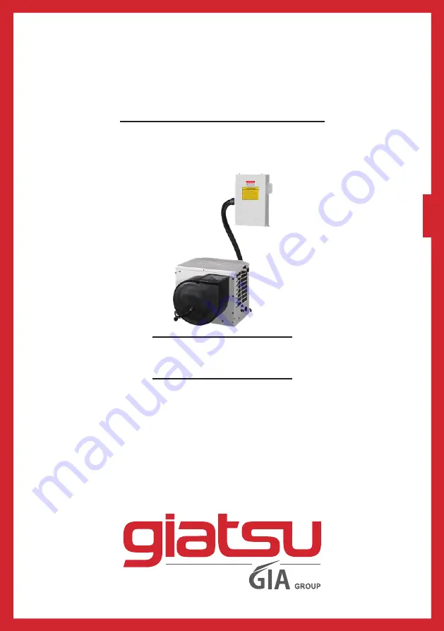
OWNER’S AND INSTALLATION
MANUAL
SPECIAL
ENGLSI
H
MARINE T
YPE AIR CONDITIONER
GIA-MAB-O-05Y01
|
GIA-MAB-O-09Y01
GIA-MAB-O-12Y01
GIA-MAB-O-16Y01
Thanks for choossing our product.
Please, read carefully this manual
before using the product
Page 1: ...TALLATION MANUAL SPECIAL ENGLSIH MARINE T YPE AIR CONDITIONER GIA MAB O 05Y01 GIA MAB O 09Y01 GIA MAB O 12Y01 GIA MAB O 16Y01 Thanks for choossing our product Please read carefully this manual before using the product ...
Page 2: ...rilles and Transition Boxes 7 3 10 Ducting 8 3 11 Seawater Pump and Plumbing 8 3 12 Electrical Connections Grounding and Bonding 10 3 13 Manual Controller Installation 11 3 14 Electric Box Installation 12 3 15 Installation Checklist Review Prior To Installation 12 3 16 Wiring Diagrams 13 4 Operation 14 4 1 Manual Controller Operation 14 4 2 Power ON OFF 15 4 3 FAN Control 15 4 4 Temperature Settin...
Page 3: ...utton Function and Description Cover Open 20 5 4 COOL Mode Operation 20 5 5 HEAT Mode Operation 20 5 6 DEHUMIDIFY Mode Operation 20 5 7 FAN Mode Operation Procedure 20 5 8 Battery Replacement in Remote Controller 21 6 Troubleshooting 22 7 Maintenance 24 7 1 Reversing Valves 24 7 2 Seawater Strainer 24 7 3 Blowers 24 7 4 Condenser Coil Cleaning 24 7 5 Return Air Filters 24 7 6 Winterization 24 ...
Page 4: ...Non volatile memory Low voltage display panel LED cabin temperature displayed in Fahrenheit or Celsius Multiple fan speed selections Compressor pressure fail safe protection Moisture mode cycle for humidity control This manual is intended to provide the information necessary to ensure proper installation operation and maintenance of the unit Improper installation can result in unsatisfactory perfo...
Page 5: ...COIL The seawater pump circulates cool seawater through the inner tube in the condenser coil this cools the refrigerant and condenses it into a liquid The heat from the refrigerant is exchanged to the seawater and discharged overboard The liquid refrigerant is then passed through the EVAPORATOR COIL and the cycle repeats removing heat from the cabin air lowering its temperature The cooled air is b...
Page 6: ...Y IMPORTANT Never install your air conditioner in the bilge or engine room areas Ensure that the selected location is sealed from direct access to bilge and or engine room vapors Do not terminate condensate drain line within 3 914mm of any outlet of engine generator exhaust system compartment housing an engine or generator or in a bilge unless the drain is connected properly to a sealed condensate...
Page 7: ... 1990 Public law 101 549 title IV section 608 c Failure to comply may result in severe penalties including fines and imprisonment CAUTION To minimize the hazard of electrical shock and personal injury this component must be effectively grounded Refer to the installation guidelines for further information Caution High compressor temperature is normal Do not touch 3 3 The size of Sealed room The siz...
Page 8: ...ill prevent short or premature cycling Tools required Screws drivers Pliers Pipe wrench Wire cutters crimpers Drill 7 8 bit Jigsaw Duct tape Electrical tape Teflon tape Bedding compound to seal thru hull fittings Hardware to secure unit pump strainer grilles control panel The unit should be positioned on a firm level horizontal surface and the condensate drain line should run downward from the uni...
Page 9: ... steps below to connect the water inlet outlet hose with the double tube heat exchanger of units 1 Remove screws on the outer casing 2 Remove the outer casing of the unit and then connect the water inlet outlet hose with the double tube heat exchanger 3 Reinstall the outer casing and fasten screws ...
Page 10: ...ns 3 7 Blower Assembly You can achieve multi directional supply air discharge from a single unit by rotating the blower to the desired position It is ideal for tight installations as 180 of rotation is available with which to position the blower Its advanced design allows the blower to be easily removed for rotating or servicing by removing 4 screws Rotate the blower to allow the most direct flow ...
Page 11: ...s 8 Pull the insulation back up over the Mylar to the ring and tape this joint 9 Remove excess ducting and use the same connection method at the supply air grille 10 All ducting should Be appropriately sized for each application Run as smoothly and taut as possible Have as few bends or loops as possible Be securely fastened to prevent sagging or chafing during vessel operation Have all excess duct...
Page 12: ...Install a seawater strainer below the level of the pump with access to filter 4 Mount the pump above the strainer and at least 1 305mm below the waterline 5 Connect the seacock and strainer with an uphill run of 5 8 reinforced marine grade hose 6 Connect the discharge from the pump uphill to the bottom inlet of the a c unit s condenser coil with 5 8 hose Connect the discharge from the condenser co...
Page 13: ...er If there is only one a c installed the seawater pump does not require a circuit breaker the wiring from the seawater pump is connected to the terminal strip in the electric box If two or more a c use the same seawater pump the pump wires will be connected to a pump relay Please refer to the wiring diagram Electrical connections in the bilge and or below the waterline should use heat shrink type...
Page 14: ...D respectively These must be connected to the unit with the proper sequence otherwise it will not operate properly If the wiring sequence is incorrect the unit s compressor Scroll type only and pump if applicable will run in the reverse direction at a significantly increased noise level 3 13 Manual Controller Installation DO NOT turn the unit off and immediately turn it back on Wait at least 30 se...
Page 15: ... all hose connections Teflon tape on all threaded connections Hose runs uphill from speed scoop and sea cock to strainer pump and a c unit then downhill if possible from a c unit to overboard discharge Water flowing freely from overboard discharge while pump is running Pump relay panel if used must have its own circuit breaker sized for the pump 20 amp max All metal fittings should be bonded 3 15 ...
Page 16: ...s Ducting is pulled taut straight smooth and properly connected with no excess 3 15 5 Quick Start Operations Checklist Ensure seawater intake ball valve sea cock is open Turn on the a c circuit breaker If the seawater pump has its own circuit breaker make sure to turn it on Turn the system on Set the desired cabin temperature set point Check for a steady solid stream of water from the overboard di...
Page 17: ...MAB O 16Y01 The specification of power cord is AWG12 3 3 2 5 The diagram of power supply is below Power Supply 4 Operation 4 1 Manual Controller Operation CAUTION Don t install the manual controller in a location where it can get wet Don t knock throw or open the manual controller frequently ...
Page 18: ...ller will display the setting status before power off automatically and if the operation status before power off is on the fan runs at once after 1 minute the compressor shall automatically run in the operation status before power off The units has not been set up the time of starting interval In cooling heating dehumidify mode the pump starts before the compressor starts stops after 5 seconds del...
Page 19: ...be set In HEAT mode the LED marked will be light when the set temperature is higher than the room temperature When the setting temperature is lower than the room temperature it will not run In AUTO mode the LED marked AUTO will be light and the room temperature will be displayed The temperature cannot be set as the system will run automatically in the appropriate mode according to the contrast bet...
Page 20: ... When the value be displayed by flashing nixie tube then to shield each signal of wireless remote controller excepting to press the button and fan speed button at the same time and to shield other buttons After manual controller powered on if there is wireless remote controller or at the same time to press other buttons except the button and fan speed button simultaneously and then press the butto...
Page 21: ...ion only is available in the same yacht and there are should be two or more units installed After the starting time interval be set up after powered off and re powered on Units will delay 3min and base on this it will delay for a while then can start up the delay time is called time of starting interval 5 Accessories ACCESSORIES ITEM QUANTITY 1 Mounting Bracket 4 2 Fuse 2 3 Remote controller 1 4 B...
Page 22: ...mode pressing button once TEMP increase 1 by TEMP button and decreases 1 by pressing button once COOL MODE SET Temp 61 F 86 F or16 C 30 C 61 F 86 F or16 C 30 C HEAT MODE SET Temp 61 F 86 F or16 C 30 C DEHUMIDFY MODE function in this A C unit Note there is no swing MODE F o OPER ON OFF ON OFF button Press this button to turn on or turn off the unit HEAT mode FAN mode DRY mode COOL mode Press this b...
Page 23: ...ture is lower than set temperature the compressor stops and only the fan will run Set temperature should be in range of 61 F to 86 F or 16 C to 30 C 5 5 HEAT Mode Operation If room temperature is lower than set temperature the unit runs in HEAT mode If room temperature is higher than set temperature the unit will shut off and the fan will run Set temperature should be in range of 61 F to 86 F or 1...
Page 24: ... 3 The LCD will show all the functional figures and letter codes after the batteries are installed Wait approximately 10 seconds for normal use 4 The life span of batteries is approximately 1 year Depending on usage 5 If the remote controller will not be used for an extended period of time please remove the batteries to prevent damage to the controller 6 The operation of the remote controller shou...
Page 25: ...cooling or below in heating ambient temperature Lower or raise set point Obstructed seawater flow Clean seawater strainer Check for obstructions at speed scoop thru hull inlet Check for a good steady flow from the overboard discharge Seawater pump maybe air locked Remove hose from pump discharge to purge air from line Refrigerant gas leaked Check a c unit for refrigerant oil leakage call service t...
Page 26: ...low coil to defrost see below Humidity level too high Close hatches and doors When all else fails Switch a c to heat until ice melts or use hair dryer to melt Check your specific control troubleshooting section System runs continuously Set point temperature is improperly set too low for cooling or too high for heating Raise or lower set point Porthole or hatches open Close all port holes and hatch...
Page 27: ... container filled with a 5 solution of muriatic or hydrochloric acid and fresh water or use a premixed over the counter solution Use a large container as possible to hold the solution 5 25 gallons CAUTION avoid spilling or splashing the solution Remember to wear all necessary protective gear i e approved safety goggles and chemical resistant gloves Follow all warnings and recommendations given by ...
Page 28: ...od of choice By this the anti freeze solution will displace any water trapped and eliminate the possibility of freezing in hidden areas In addition since the seawater pump utilizes a magnetically driven impeller the impeller should be removed from the wet end assembly Wiped with a solution and stored in a warm dry area until commissioning takes place Collect all discharged liquids and recycle or d...
Page 29: ...C Industria 13 l Polígono Industrial El Pedregar 08160 Montmeló Barcelona Spain Phone 0034 93 390 42 20 Fax 0034 93 390 42 05 info giatsu com www giatsu com ...