Operating manual
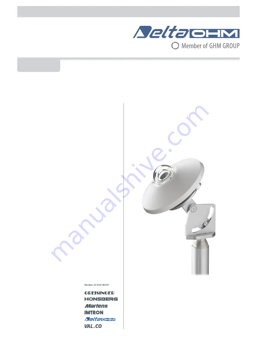
Pyranometer
LPPYRA10
www.deltaohm.com
English
Keep for future reference.
Page 1: ...Operating manual Pyranometer LPPYRA10 www deltaohm com English Keep for future reference...
Page 2: ...NS 12 4 5 LPPYRA10S12 CONNECTIONS 13 4 6 LPPYRA10ACS 4 CONNECTIONS 14 5 MEASUREMENT IN THE MODELS WITH ANALOG OUTPUT 15 5 1 LPPYRA10 15 5 2 LPPYRA10AC S 4 15 5 3 LPPYRA10AV 4 15 6 RS485 MODBUS RTU OUT...
Page 3: ...TIVE with 4 20 mA CURRENT output 0 4000 W m2 LPPYRA10ACS ACTIVE with 4 20 mA CURRENT output 0 2000 W m2 and RS485 Modbus RTU output LPPYRA10ACS4 ACTIVE with 4 20 mA CURRENT output 0 4000 W m2 and RS48...
Page 4: ...s greater than 99 8 Figure 2 1 shows the relative spectral sensi tivity of the LPPYRA10 pyranometer and a standard solar spectrum Fig 2 1 LPPYRA10 pyranometer relative spectral sensitivity blue line c...
Page 5: ...al condensation forming on the internal side of the dome under cer tain climatic conditions silica gel tablets are inserted inside the pyranometer to ab sorb humidity Fig 2 3 scheme of principle LPPYR...
Page 6: ...a coin 3 Remove the cartridge perforated cap 4 Open the sachet containing silica gel supplied with the pyranometer 5 Fill the cartridge with the silica gel crystals 6 Close the cartridge with its own...
Page 7: ...tioned so that its connector is pointed to the North Pole if the instrument is used in the Northern Hemisphere and to the South Pole if used in the Southern Hemisphere In any case it is better to foll...
Page 8: ...HD2003 77C HD2003 83 HD2003 83 1 HD2003 85K D HD9007 LPPYRA10 HD9007T29 1 C A B TP32MTT 03 C 80 MAX int M37 x 2 Fig 3 3 fixing accessories A Palo 750 mm B Raccordo di base C Piastra di supporto gradua...
Page 9: ...LPPYRA10 9 V2 6 Fig 3 4 fixing accessories...
Page 10: ...PPYRA10AV 4 the housing is not connected to the connector Inside the housing there is a surge protector connected between the housing itself and the electronic circuit powered models or the ca ble shi...
Page 11: ...n the ordered output and requires external power supply 10 30 Vdc for 0 1 V and 0 5 V outputs 15 30 Vdc for 0 10 V output It is to be connected to a power supply and an instrument with voltage input a...
Page 12: ...S485 A Brown 5 RS485 B White 6 Housing Cable shield SH Black 7 Not connected 8 Not connected Shield Shield Lmax 1200m B A 1 2 3 4 5 6 7 8 B A SGND Vdc GND GND Vdc A B SH R 220 T R 220 T Fig 4 4 LPPYRA...
Page 13: ...7 8 GND Vdc SDI 12 SDI 12 BUS Vdc GND SH Fig 4 5 LPPYRA10S12 connections More SDI 12 sensors can be connected in parallel The distance between a sensor and the acquisition system data logger should n...
Page 14: ...r 1 Power supply negative GND Blue 2 Power supply positive Vdc Red 3 Digital and analog ground SGND Black 4 RS485 A Brown 5 RS485 B White 6 Housing Cable shield SH Black thick wire 7 Analog output pos...
Page 15: ...e range The irradiance Ee is obtained by measuring with a multimeter the current Iout absorbed by the sensor and applying the following formula Ee 125 Iout 4 if f s 2000 W m2 Ee 250 Iout 4 if f s 4000...
Page 16: ...y to install the related USB drivers in the PC NOTES ON THE INSTALLATION OF UNSIGNED USB DRIVER before installing unsigned USB driver into operating systems starting from Windows 7 it is necessary to...
Page 17: ...ta bits no parity 2 stop bits n 2 8 E 1 8 data bits even parity 1 stop bit n 3 8 E 2 8 data bits even parity 2 stop bits n 4 8 O 1 8 data bits odd parity 1 stop bit n 5 8 O 2 8 data bits odd parity 2...
Page 18: ...4 3 Status register bit0 1 solar radiation measurement error bit2 1 configuration data error bit3 1 program memory error 16 bit Integer 5 4 Average values of the last 4 measurements 16 bit Integer 6...
Page 19: ...ing table The following table reports the SDI 12 commands available For consistency with SDI 12 standard documentation the instrument address is indicated in the table with the letter a SDI 12 Command...
Page 20: ...al temperature in the set unit of measurement default C Example of response 0 0 228 7 3 294 25 0 probe address 0 content of the status register 0 irradiance 228 7 W m2 signal internal level 3 294 mV i...
Page 21: ...execute the measurement aD0 a v v CR LF with v v signal internal level in mV Example of response 0 3 294 probe address 0 signal internal level 3 294 mV Reads the measurement In addition to the above m...
Page 22: ...end the command aXSCAL USER ON note a instrument address 2 Send the command aXSCFD to set C or aXSCFE to set F 3 Send the command aXSCAL END For more information about the SDI 12 protocol visit the we...
Page 23: ...n this case the performed reading is highly over estimated To minimize the condensation the pyranometer is provided with a cartridge containing dessicant material silica gel The efficiency of the sili...
Page 24: ...Consumption 200 A for the version LPPYRA10S12 Connection 4 or 8 pole M12 connector depending on the model Dimensions Fig 3 2 Weight 750 g approx passive version with shade disk 900 g approx active ver...
Page 25: ...well as the specific measures described in this manual are followed The instrument proper operation and operating safety can be ensured only in the cli matic conditions specified in this manual Do not...
Page 26: ...ther end Length 2 m CPM12AA4 2 5 m CPM12AA4 5 or 10 m CPM12AA4 10 For LPPYRA10 LPPYRA10AC 4 and LPPYRA10AV 4 CPM12 8D Cable with 8 pole M12 connector on one end open wires on the other end Length 2 m...
Page 27: ......
Page 28: ...anty included in the manual of the product For any dispute the competent court is the Court of Padua The Italian law and the Convention on Contracts for the International Sales of Goods apply TECHNICA...