G-Cam/EBC-2112 Full HD Box IP Camera Quick Guide
3)
Attach your lens to the lens mount by rotating the lens clockwise.
4)
Manually adjust the zoom and focus of the image with the zoom and focus lever on the lens.
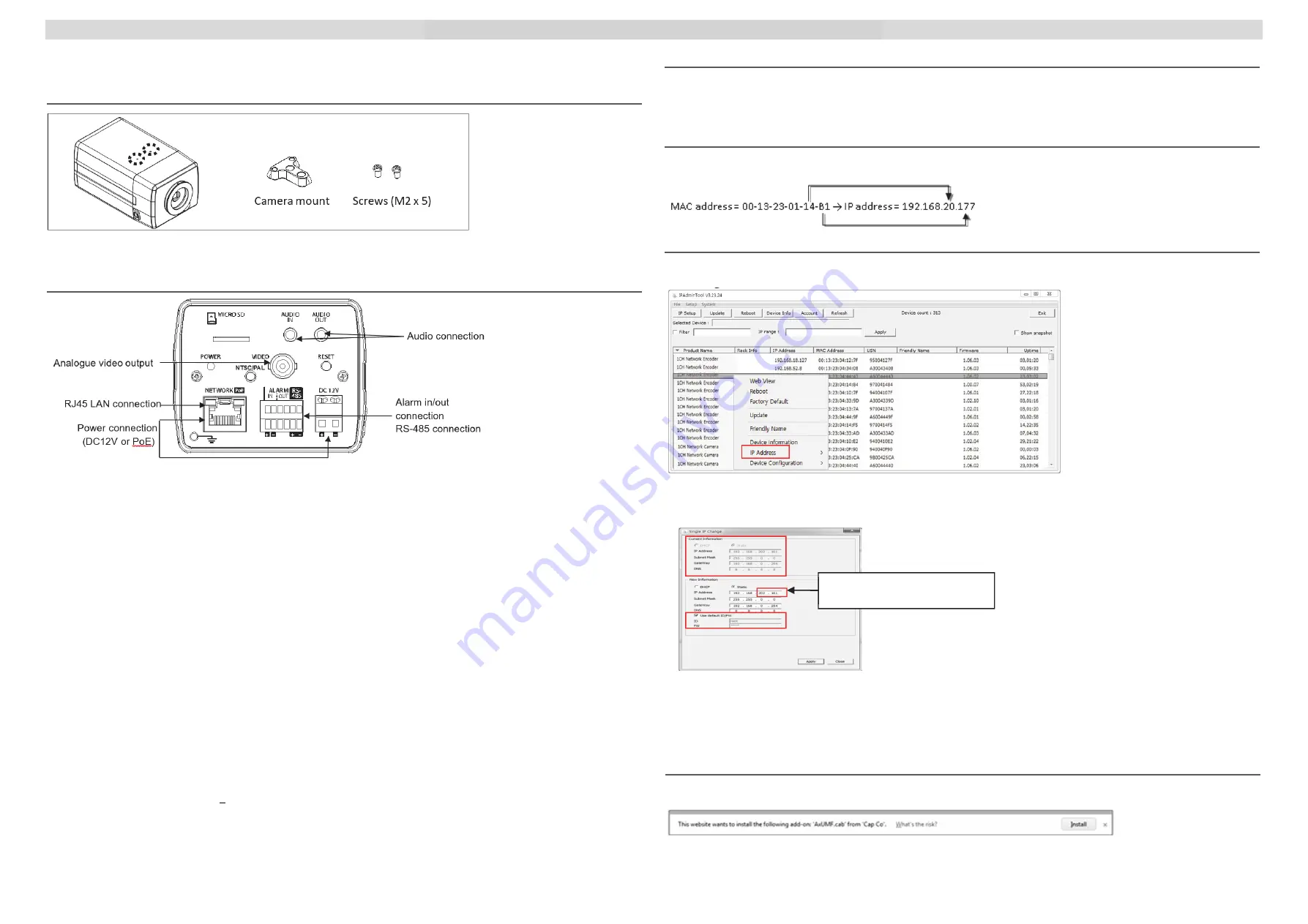
Installing the camera mount
Attach the provided camera mount to the mount screw points in the dashed circles by using the provided two
screws, and rotate the screws clockwise to tighten the camera mount.
Connections
Power Connection
The device can be powered either via 12VDC or PoE.
To operate your camera using 12VDC, make sure that the polarity is correct before connecting the power cable.
Incorrect connection may cause damages to the device.
LAN Connection
The device has an RJ45 LAN connector for 10/100 Base-T Ethernet. Use the Ethernet cable (RJ45) to connect the
device to a hub or a router in the network. When the LAN cable is connected, the orange LED light will become solide
and green LED will blink every 250 millisecond.
Analogue Video Output Connection
Use a 75 ohm video coaxial cable to connect to a monitor’s analog video input and check the camera’s connection
and its image focus at the installation site.
To see the analogue video output, be sure to press the output configuration button (PAL/NTSC button).
Pressing the button cycles through no video out, PAL, and NTSC.
Audio Connection
The camera provides a mono audio input and output. Due to low audio output power, an amplified speaker is
recommended for enhanced sound.
Alarm Input / Alarm Output / RS-485
‐
Alarm Input
Alarm Input can be connected to either a voltage type sensor or a relay type sensor like the following figures. Settings
can be done through the camera’s web page.
Input voltage range: 0VDC minimum to 5VDC maximum, Max 50mA
‐
Alarm Output
Only the relay type is supported.
Relay Rating: Max 24VDC 50mA
‐
RS485
The RS-485 serial port consists of TRX+(RX+) and TRX-(RX-).
Please refer to the connection section in the product’s installation guide on supplied CDROM for the instructions.
Setting up Network Environment
The default IP address of the device is 192.168.XXX.XXX. Users can identify the IP address of the device by
converting the MAC address’s hexadecimal numbers to decimal numbers. The MAC address can be found on the
bottom of the device. Be sure that the device and the PC are on the same network area before the installation.
Generic IP Environment
Convert the device’s MAC address to the IP address. Refer to the Hexadecimal-Decimal Conversion Table at the end
of this guide.
Convert the last two sets of hexadecimal numbers to
decimal numbers.
IPAdmin Tool
IPAdminTool is a management tool to automatically scan all the network products for the devices’ administrative tasks,
which include network configurations, firmware update, device reboot, factory default, and device configuration.
To modify the device’s default IP address for a customized network area:
1)
Find the device from the IPAdminTool’s list, and highlight the device’s name.
2)
Right-click the mouse, select
IP Address
, and select
Single
; The IP setup window will appear.
3)
On the New Information table in the Single IP Change window, modify the last two sets of the device’s IP address,
and modify the rest parts including subnet mask, gateway, and DNS if necessary by checking the user/ PC network
area information.
4)
Make sure to input the correct ID and PW of the device (default: root / admin).
5)
Click
Apply
to complete the modification.
Viewing video on Webpage
Once the device’s IP address has been identified, type the URL in a web browser to access the camera. At the initial
access, the installation window may pop up.
1)
When the browser asks to install the AxUMF software, click the Install button to proceed.
2)
When the Setup installation pop-up window appears, click the Install button to preceed with the rest of the installation.
Give a new unique IP address by
modifying the last two sets.
2
3