GeoVision GV-AS1620 User Manual Download Page 13

 
         The Web Interface 


Chapter 3  The Web Interface 

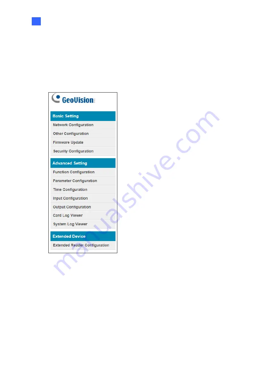
After installing the controller on the network, you can configure the controller’s settings on 
the Web interface. The left menu of the Web interface is divided into three sections: 

Basic 

Setting

Advanced Setting 

and 

Extended Device


                Figure 3-1 


Summary of Contents for GV-AS1620

Page 1: ...GV AS1620 Controller Before attempting to connect or operate this product please read these instructions carefully and save this manual for future use User s Manual AS1620V10 A...

Page 2: ...is assumed for incidental or consequential damages arising from the use of the information or products contained herein Features and specifications are subject to change without notice Note No memory...

Page 3: ...ddress 5 2 3 Configuring DDNS Connection 5 Chapter 3 The Web Interface 9 3 1 Basic Settings 10 3 1 1 System Setup 10 3 1 2 Firmware Update 12 3 1 3 Security Configuration 13 3 2 Advanced Settings 13 3...

Page 4: ...and RS 485 outputs that can be connected to any standard access control panel GV RU9003 GV RU9003 is a Radio Frequency Identification RFID reader of ISO 18000 6C EPC GEN2 standard Designed for parking...

Page 5: ...cate an access granted and denied 1 1 Key Features One door IP controller entry and exit 3 types of interfaces Wiegand RS 485 and TCP IP supporting 2 readers for each interface 4 digital inputs for do...

Page 6: ...rs DO 4 LED for Access Denied DI 4 Tamper Contact Control Definition DC 12V Power output for compatible devices connected Web Setting Switch GUI security lock Switch on to lock all system configuratio...

Page 7: ...connected to a network with a DHCP server a dynamic IP address will be assigned to the controller See 2 1 Checking the Dynamic IP Address to look up its IP address 2 When the DHCP server on your netw...

Page 8: ...button to search for the IP devices connected in the same LAN 3 Click the Name or Mac Address column to sort 4 Find the controller with its MAC address click on its IP address and select Web Page Figu...

Page 9: ...ction select Disable Type the static IP address information including IP Address Subnet Mask Default Gateway and Domain Name Server 4 Click Submit When the setting is complete the Status field will in...

Page 10: ...V2 page appears Note 1 Dynamic DNS uploads IP addresses over the Internet through ports 80 and 81 If your controller is connected behind a router or firewall make sure ports 80 and 81 are enabled Dyna...

Page 11: ...e the characters or numbers shown for word verification and click Send 4 When the registration is complete this page will appear The Hostname is the domain name consisting of the registered username a...

Page 12: ...address The login dialog box appears 2 Type the username and password of the controller and click OK The Network Configuration page appears 3 Select Enable DDNS 4 Type Host Name User Name and Passwor...

Page 13: ...face After installing the controller on the network you can configure the controller s settings on the Web interface The left menu of the Web interface is divided into three sections Basic Setting Adv...

Page 14: ...on covers general system settings firmware update and user account settings For details on Network Configuration refer to Chapter 2 Installing on a Network 3 1 1 System Setup In the left menu click Ot...

Page 15: ...current firmware version of the controller Reboot System Performs a warm boot of the controller This operation will keep the current system configuration Configuration Control Default Value Resets all...

Page 16: ...he firmware file 3 Click Upload This update process may take 60 seconds to complete 4 When the Update is complete you will be asked to reboot the system 5 Click OK to restart the controller Note 1 Mak...

Page 17: ...d to alphabets and numbers Figure 3 4 3 2 Advanced Settings Under Advanced Settings you can configure the door settings turn on Alarms set the device time edit the input function and view logs Changes...

Page 18: ...14 3 2 1 Function Configuration In the left menu click Function Configuration This page appears Figure 3 6...

Page 19: ...Grants access after the card is presented or a passcode is entered and ignores the authentication schedule of GV ASManager Fixed Card Mode PIN Mode Grants access after the card is presented and the c...

Page 20: ...access logs from the same card via Wiegand port A or B within the duration set Wiegand A B Filter Duration Set the duration of filter from 3 60 seconds Camera Mapping You can assign a camera to captur...

Page 21: ...re 3 6 Option Description Anti Passback Enables or disables the Anti Passback function Lock Reset Time Sets the time 1 to 600 sec that a door remains open after which the door will automatically be lo...

Page 22: ...ise even though the alarm conditions are met the expected alarm will not be triggered The default settings for all the alarms are set to NO Option Description Held Open This alarm activates whenever t...

Page 23: ...f the controller Local Time Disable Disable the manual configuration of time and date Setup Configure the time and date of the controller manually You can click Current local time to synchronize the c...

Page 24: ...the controller You set the input status to either NO normally open or NC normally close Figure 3 9 3 2 5 Output Configuration In the left menu click Output Configuration to define the output devices...

Page 25: ...when the controller is disconnected from GV ASManager Only up to 100 log entries of Event Log Access Log on the Web interface can be retrieved at a time Figure 3 11 3 2 7 System Log Viewer In the left...

Page 26: ...and leave the serial number field blank Note that the ID number located next to the serial number field needs to match the reader s ID number defined by the dip switches on the reader GV GF1921 GF192...

Page 27: ...d the controller respectively This procedure can determine if the problem is caused by faulty devices and incorrect network settings 1 Disconnect the hub or switch which connects both the GV ASManager...

Page 28: ...ID 1 Network TCP IP IP 192 168 X XXX Port 4000 User admin Password admin Crypto key 12345678 Figure 4 3 7 The connection between the GV ASManager and controller should be established under the LAN wi...

Page 29: ...IP address that is NOT used by another device under the LAN See Figure 4 1 5 Log in the controller The Network Configuration page appears 6 In the IP address field give the controller an IP address th...

Page 30: ...ears It may be the card format is not compatible with the controller Make sure the card format is 64 bits Otherwise send us the related information of your card format so that we can customize the set...

Reviews: