

GMS
plus
Quick User Manual
User MUST follow all instructions under the
WARNINGS AND SAFETY
section in the user manual !
Foreword
This manual is provided as a brief guideline to give an overview
of the first steps and it is not intended to cover all the different
circumstances. Please check the
GMS
plus
User Manual
for
details.
Step 1.
Unpacking
The GMS
plus
is shipped in a standard packing box containing all
the typical accessories. Some specific options (such as the
external battery) may be supplied in a separate box.
The packing box must be inspected for any external damage and
any damage should be immediately reported to the forwarder.
The contents of the packing box can be checked according to the
order and the packing list. Verify that none of the items have
physical damage. Keep the packing box for transportation to the
final location of the instrument.
Step 2.
Installation Organisation
Before proceeding further please revise the figure at the end of
this manual, which illustrates standard and optional connections
of the instrument. This way you can familiarise yourself with the
GMS
plus
and the options you have received for connectivity.
The following items are required for a typical installation:
•
Drill, drill bits, screws and tools for mounting or levelling
•
Compass or building references for the axis orientation
•
Latest version of GeoDAS software and manual (check
also on our web site
www.geosig.com
)
•
Computer with CD-ROM drive, serial (COM) port and
Ethernet
•
Any accessories delivered with the GMS
plus
(refer also to
the figure at the end of this manual)
We strongly recommend installing GeoDAS (see Step 8) on the
computer prior going to the final installation site. Also it is a good
practice to perform a first test of the entire system in the office in
order to get familiar with it.
Step 3.
Site Preparation
The installation site should be selected away from mechanical
and electrical noises and interference sources. The distances
must be evaluated for AC power source, GPS location, phone line
etc.; in order to have sufficient cable lengths.
Make sure that:
•
There is AC power near the instrument (either for GMS
plus
operation or for the drill during installation).
•
If no AC power is present, make sure you have the
required tools for installation accordingly.
•
Clean and free space is available on the foundation.
The instrument itself can be mounted in any orientation desired
under the condition that it does not have an internal battery. In
cases where the instrument has an internal battery it must always
be mounted flat on the ground in a non-tilted position.
Step 4.
Physical Installation
a
For your convenience a training video explaining the
installation of the GMS-xx and GMS
plus
is available at
www.geosig.com
à
Support
à
‘How To …’ Videos
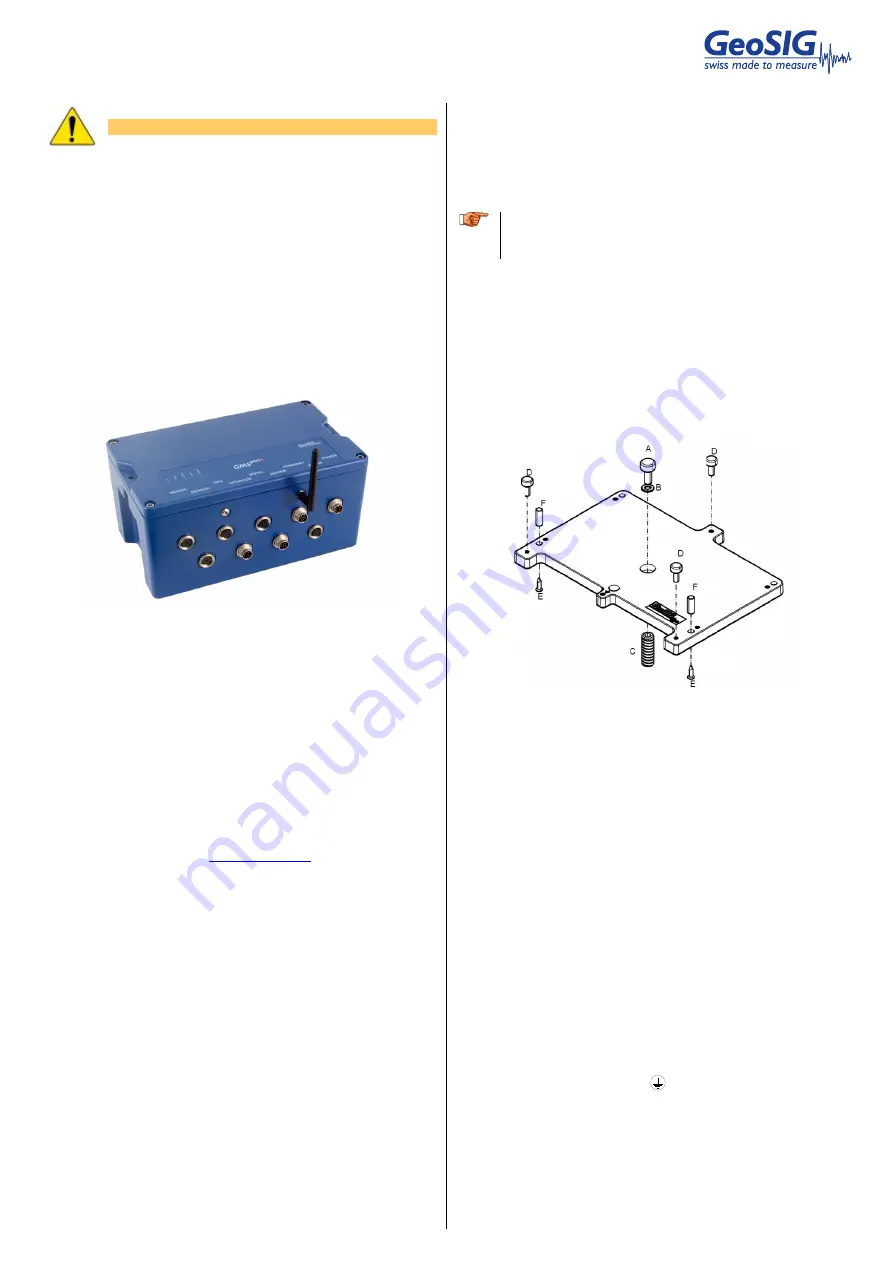
The GMS
plus
has a base plate that must be first fixed to the
ground where the instrument can be mounted on. For this
purpose, the base plate has a central fixing hole (suitable for 8
mm screws) and three levelling screws.
Base plate preparation:
•
Mount the 3 levelling screws
(D)
.
•
Check that the 4 M6 threads for the instrument fixing are
free from dust.
•
Mount the 2 polarization pins on the base plate on the
sides where the connectors will be
(E/F)
.
Drill an 11 mm hole in the concrete with a typical depth of 50 mm
for the supplied M8 concrete anchor
(C)
. Clean the whole area of
dust. Insert the concrete anchor into the hole. Mount the plate in
place and insert the M8 fixing screw
(A/B)
in its hole. Turn the
plate so it is oriented according to the requirement. Make a
coarse levelling of the plate
(D)
. Start fixing the plate by tightening
the M8 central screw
(A)
. Check regularly the plate orientation
and level till the plate is rigidly fixed
(D)
. Remove the cover of the
instrument and put it on the mounting plate using the 4 screws
and washers to fix it. Take care about the 2 orientation pins on
the plate
(E/F)
.
Step 5.
Power Connection
The instrument should be powered from 110 VAC up to 230 VAC,
50 or 60 Hz through the external AC/DC converter or any other
option described at the end of this manual. The power cable is
delivered usually with a suitable plug for the country (e.g. CH, EU,
US). If not usable, the cable can be cut and an appropriate local
power plug has to be purchased locally. The power plug must be
wired by a qualified electrician as:
•
Brown or Black wire
à
Phase
•
Blue or White wire
à
Neutral
It is necessary to connect the
M6 earth screw on the base
plate, to the local earth. Make sure the green AC indicator is ON.
Step 6.
GPS Connection
The GPS module should be fixed at a location where satellite
signals could easily be received. If the GMS
plus
is installed inside
a building or a basement, the GPS module should be installed
outside. Once fixed, the GPS can be connected to the GPS
connector.


