


3
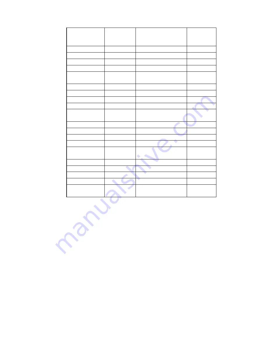
Terminal
Block Position
Channel
Number
Description
Cable
Wire
Color
VW1+
1
Vibrating Wire +
RED
VW1-
1
Vibrating Wire -
BLACK
TH1+
1
Ther
WHITE
TH1-
1
Thermistor -
GREEN
SHLD1
1
Analog Ground
(shield)
BARE
WIRE
VW2+
2
Vibrating Wire +
RED
VW2-
2
Vibrating Wire -
BLACK
TH2+
2
Ther
WHITE
TH2-
2
Thermistor -
GREEN
SHLD2
2
Analog Ground
(shield)
BARE
WIRE
VW3+
3
Vibrating Wire +
RED
VW3-
3
Vibrating Wire -
BLACK
TH3+
3
Ther
WHITE
TH3-
3
Thermistor -
GREEN
SHLD3
3
Analog Ground
(shield)
BARE
WIRE
VW4+
4
Vibrating Wire +
RED
VW4-
4
Vibrating Wire -
BLACK
TH4+
4
Ther
WHITE
TH4-
4
Thermistor -
GREEN
SHLD4
4
Analog Ground
(shield)
BARE
WIRE
Table 1 - Transducer Cable Connections
5)
Tighten the nuts on the cable fittings so that they securely grip the cables.
This must
be done to ensure that water does not enter the enclosure.
(Beware of
overtightening, which may damage the plastic threads.)
2.1.2 10-pin Bulkhead Models (8002-4A-1, 8002-4A-2, 8002-4A-3)
Transducers are attached to the datalogger with 10-pin Bulkhead connectors. Align the
grooves on the transducer connector (male), with the connector on the unit (female). Push
the connector into place and then twist the outer ring of the male connector until it locks.


