43
APPENDIX B. CONNECTOR PINOUTS
B.1 Transducer Cable Connections
Terminal Block
Position
Channel
Number
Description
Cable Wire
Color
VW1+
1
Vibrating Wire +
RED
VW1-
1
Vibrating Wire -
BLACK
TH1+
1
Ther
WHITE
TH1-
1
Thermistor -
GREEN
SHLD1
1
Analog Ground (shield)
BARE WIRE
VW2+
2
Vibrating Wire +
RED
VW2-
2
Vibrating Wire -
BLACK
TH2+
2
Ther
WHITE
TH2-
2
Thermistor -
GREEN
SHLD2
2
Analog Ground (shield)
BARE WIRE
VW3+
3
Vibrating Wire +
RED
VW3-
3
Vibrating Wire -
BLACK
TH3+
3
Ther
WHITE
TH3-
3
Thermistor -
GREEN
SHLD3
3
Analog Ground (shield)
BARE WIRE
VW4+
4
Vibrating Wire +
RED
VW4-
4
Vibrating Wire -
BLACK
TH4+
4
Ther
WHITE
TH4-
4
Thermistor -
GREEN
SHLD4
4
Analog Ground (shield)
BARE WIRE
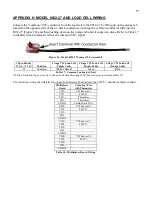
Table 10 - Transducer Cable Connections
B.2 RS-232 Connector Pinout (8002-4-1)
The mating 10 pin Bendix plug is part number PT06F-12-10P.
10 Pin
Bendix
Internal Wire
Color
PCB connector J5
pin
Description
A
Brown
1
Ground
B
Red
2
Tx
C
Orange
3
Rx
D
Yellow
4
RTS
E
Green
5
CTS
F
Blue
6
N/C
G
Violet
7
DTR
H
Grey
8
+5V
J
White
9
N/C
K
Black
10
Ground
Table 11 - RS-232 Connector Pinout


