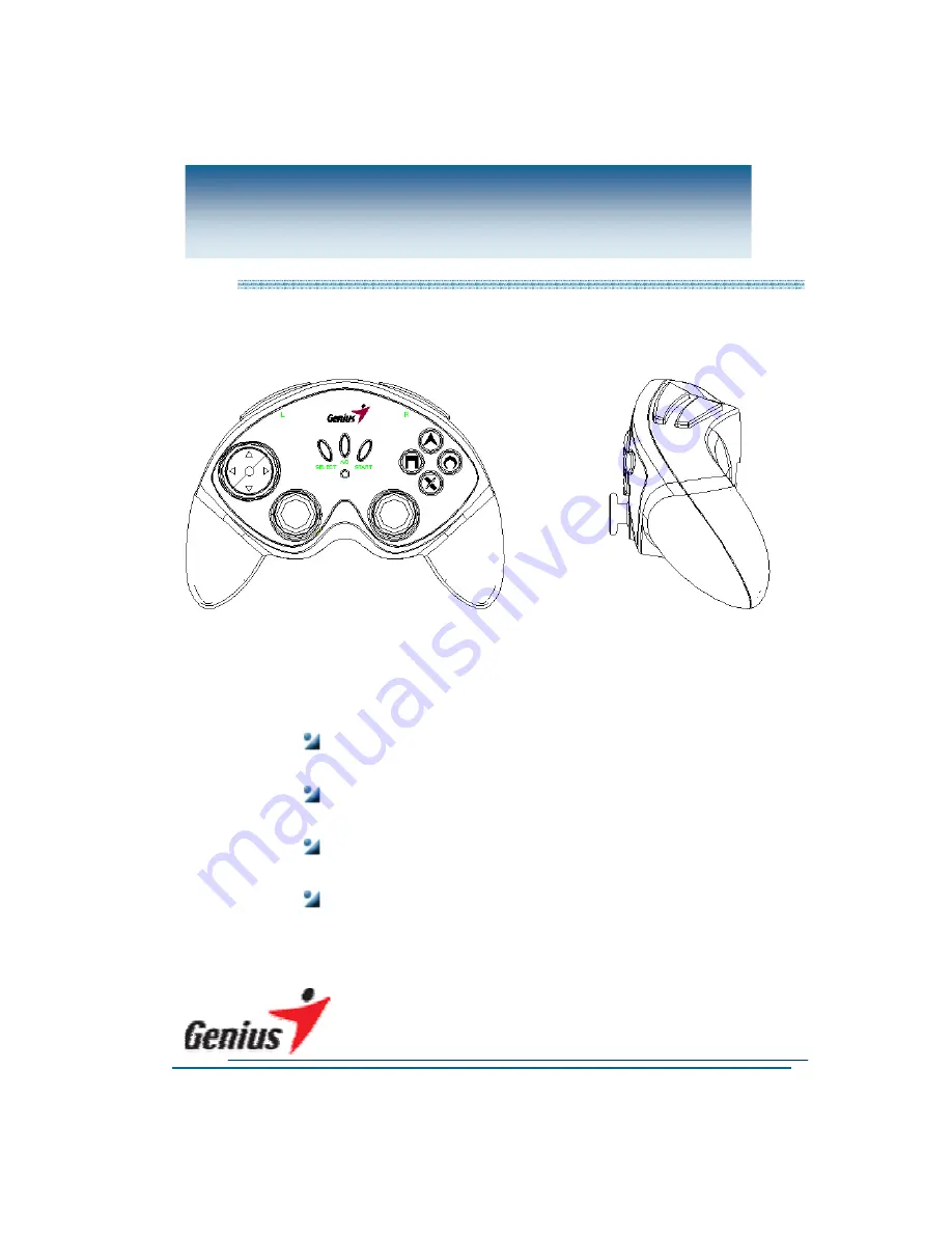
Product : Gamepad Model Name :
Max Fire G12PS
Model Number : G12PS Version Number : 01
Service Guide
Page 1: ...Product Gamepad Model Name Max Fire G12PS Model Number G12PS Version Number 01 Service Guide ...
Page 2: ...dure 5 3 2 Problem description 6 3 3 Problem solve 7 4 Assemble Disassemble 10 4 1 How to Assemble and Disassemble the pad surface 10 4 2 How to Assemble and Disassemble the PSB 11 4 3 How to Assemble and disassemble the Ministick 12 4 4 How to Assemble and Disassemble the Motors 13 4 5 How to Assemble and Disassemble the LED 14 5 Appendix 1 Part list 15 6 Appendix 2 Disassemble drawing 16 ...
Page 3: ... KYE SYSTEMS CORP 3 Service Guide 1 Revision Record Date Version Name Approve 2003 5 15 1 0 Bam Niky ...
Page 4: ...is against hardware problems of this pad 2 2 Necessary tools 2 3 Safety attention When staying for long time please check electric and power circuit Place it in flat surface and prevent it from vibration Don t drop and jolt this pad Don t remove this pad from your PS when it is using Keep this pad away wet and high temperature Screwdriver Tweezers Solder Solder torch Tin Sucker ...
Page 5: ...1 Procedure Analyze possible malfunction causes Frame the solutions and methods Replace necessary defective parts Test all function to check the pad is ok Return the pad to customers Received Defective Pad Test Check problem Function NG Function OK Function OK Function NG ...
Page 6: ...em Description 3 2 1 Ministick s function wrong 1 Can t control ministick correctly and completely 2 Ministick is no work 3 2 2 Motors are incorrect 1 One or both of two motors is no work 2 Any Motors rotation is incorrect 3 2 3 LED 1 LED isn t bright 2 LED is twinkling ...
Page 7: ...roblem Analyze the problem Judge the problem causes Solution Ministick wrong Mechanics Electronics 1 Incorrect using causes the mechanics of ministick broken 2 Out of life 1 Using for too long time causes the value of VR instable 2 Out of life Replace the Ministick Replace the Ministick ...
Page 8: ...3 2 Motors are incorrect Problem Analyze the problem Judge the problem causes Solution Any motor is no rotation Motor s Mechanics Electronics 1 Out of life 1 The cord between Motor and PCB is fall off Replace the Motor Re solder the Cord ...
Page 9: ... 9 Service Guide 3 3 3 LED Problem Analyze the problem Judge the problem causes Solution LED isn t bright Mechanics Electronics 1 Out of life 1 The cord between LED and PCB is fall off Replace the LED Re solder the cord ...
Page 10: ...ad surface Procedure Graphics 1 Disassemble 1 Turn over the pad 2 Put the pad on a flat 3 Rotate screws 4 Separate pad s covers 2 Assemble 1 Compose all parts according to disassemble drawing 2 Lock all screws firmly Attention When assembling the pad surface please put a cloth to prevent it from rub ...
Page 11: ...de 4 2 How to Assemble and Disassemble the PSB Procedure Graphics 1 Disassemble 1 Rotate the screws on the ministicks PSB 2 Assemble 1 Lock the screws Attention When rotating PSB s screws please take care other parts connected to PSB ...
Page 12: ... Procedure Graphics 1 Remove 1 Suck the point of weld of the Resonator by Tin Sucker 2 Remove the defective Ministick by Tweezers 2 Replace 1 Insert the same spec complete Ministick on the correct hole 3 Solder 1 Solder the Ministick 2 Check all points of solder is ok ...
Page 13: ...e Graphics 1 Remove 1 Suck the point of weld of the Motor s cord by Tin Sucker 2 Remove the defective Motor by Tweezers 2 Replace 1 Change a all right Motor 2 Solder the cord with the new Motor 3 Assemble 1 Put the new Motor into the seat 3 Check all points of solder is ok ...
Page 14: ... Remove 1 Suck the point of weld of the LED by Tin Sucker 2 Remove the defective LED by Tweezers 2 Replace 1 Insert the same spec complete LED on the right hole 3 Solder 1 Solder the LED 2 Check all points of solder is ok Attention When insert the LED please take care of it s height ...
Page 15: ...Name Quantity Station Spec 1 1450311R LED 1 D11 Red LED 2 151G1211 Motor1 1 Big Motor 7 5V Big motor 3 151G1221 Motor2 1 Small Motor 7 5V Small motor 4 126G1211 Ministick 2 JL JR B10K 45degree 5 22503603 Cord 2 R1 R2 L1 L2 3PIN 60mm 2MM 6 22508403 Cord 1 8PIN 8PIN 40mm 2MM ...
Page 16: ...EMS CORP 16 Service Guide 6 Appendix 2 Disassemble Drawing 412G081D 414G123D 241G1231 427G081D 241G1211 420G121 401G121D 414G124D 24153011 214G1221 241G1221 4093571D 214G1231 414G082D 214G1211 151G1211 401G082D ...