Product : Gamepad Model Name :
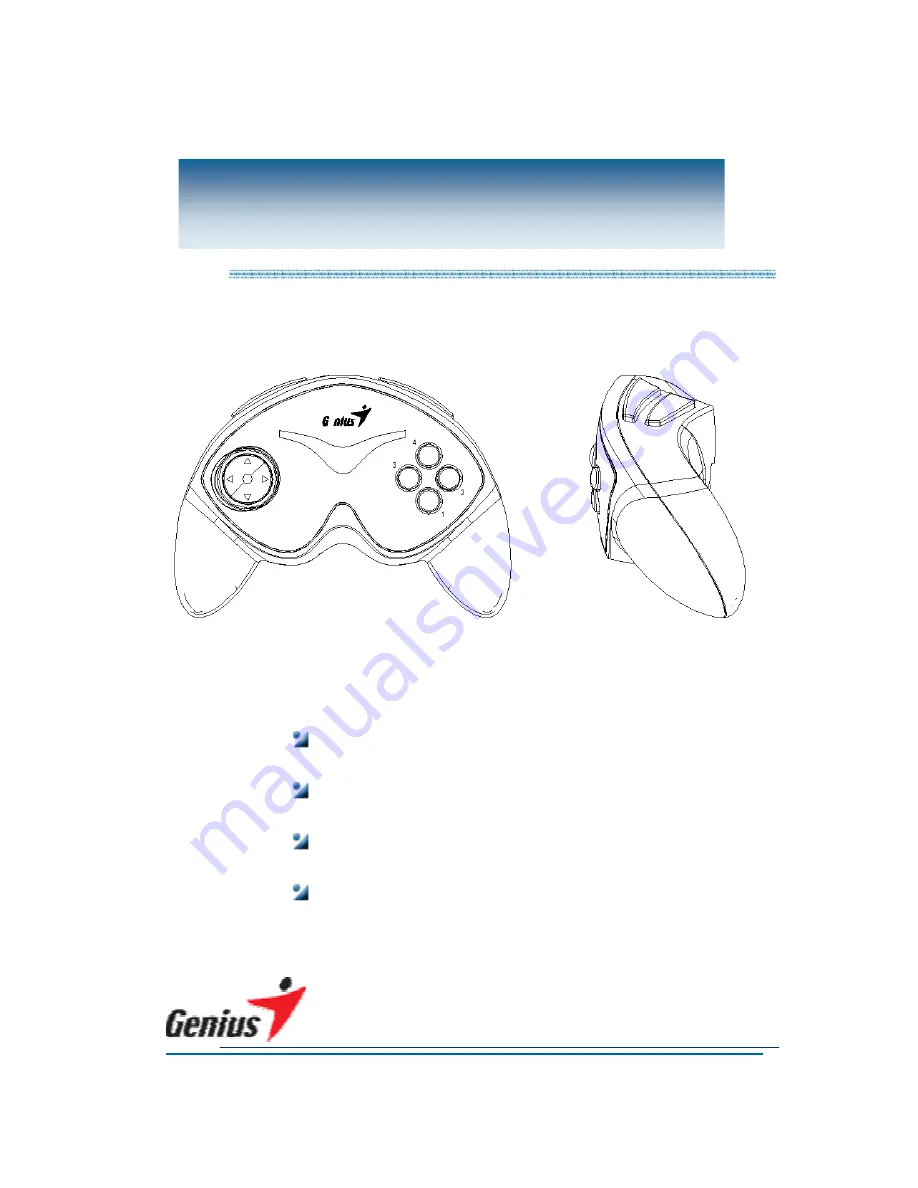
Max Fire G08XU
Model Number : G08XU Version Number : 01
Service Guide
Page 1: ...Product Gamepad Model Name Max Fire G08XU Model Number G08XU Version Number 01 Service Guide ...
Page 2: ... attention 4 3 How to handle defective returns 5 3 1 Procedure 5 3 2 Problem description 6 3 3 Problem solve 7 4 Assemble Disassemble 9 4 1 How to Assemble and Disassemble the pad surface 9 4 2 How to Assemble and Disassemble the PCB 10 4 3 How to Replace the Resonator 11 5 Appendix 1 Part list 12 6 Appendix 2 Disassemble drawing 13 ...
Page 3: ... KYE SYSTEMS CORP 3 Service Guide 1 Revision Record Date Version Name Approve 2003 5 6 1 0 Bam Niky ...
Page 4: ...is against hardware problems of this pad 2 2 Necessary tools 2 3 Safety attention When staying for long time please check electric and power circuit Place it in flat surface and prevent it from vibration Don t drop and jolt this pad Don t remove this pad from your PC when it is using Keep this pad away wet and high temperature Screwdriver Tweezers Solder Solder torch Tin Sucker ...
Page 5: ...1 Procedure Analyze possible malfunction causes Frame the solutions and methods Replace necessary defective parts Test all function to check the pad is ok Return the pad to customers Received Defective Pad Test Check problem Function NG Function OK Function OK Function NG ...
Page 6: ... Problem Description Item Problem Description 3 2 1 No any work 1 The pad s inner cable isn t connected 2 The pad s electronic circuit is ok but still no any work 3 2 2 Some buttons function wrong 1 The cords linked to PCB are unconnected ...
Page 7: ...roblem Judge the problem causes Solution No any work Resonator Cable 1 Heavy dropped cause the resonator broken 2 Out of life 3 The cord is unconnected 1 Heavy dropped cause the cable disconnected 2 Wet causes the short circuit 1 Replace the resonator 2 Re solder the cord Re solder the cable ...
Page 8: ...vice Guide 3 3 2 Some buttons function wrong Problem Analyze the problem Judge the problem causes Solution Button s function wrong Cord Button 1 The cord is broken 1 The button is loosened Re solder the cord Re set the button ...
Page 9: ...ad surface Procedure Graphics 1 Disassemble 1 Turn over the pad 2 Put the pad on a flat 3 Rotate screws 4 Separate pad s covers 2 Assemble 1 Compose all parts according to disassemble drawing 2 Lock all screws firmly Attention When assembling the pad surface please put a cloth to prevent it from rub ...
Page 10: ...ice Guide 4 2 How to Assemble and Disassemble the PCB Procedure Graphics 1 Disassemble 1 Rotate the screws on the PCB 2 Assemble 1 Lock the screws Attention When rotating PCB s screws please take care other parts connected PCB ...
Page 11: ...or Procedure Graphics 1 Remove 1 Suck the point of weld of the Resonator by Tin Sucker 2 Remove the defective Resonator by Tweezers 2 Replace 1 Insert the same spec complete Resonator on the right hole 3 Solder 1 Solder the Resonator 2 Check all points of sold is ok ...
Page 12: ... KYE SYSTEMS CORP 12 Service Guide 5 Appendix 1 Part List Item Part No Name Quantity Station Spec 1 14960040 Resonator 1 Y1 6MHz 2 22503603 Cord 2 SW5 SW6 SW7 SW8 3PIN 60mm 2MM ...
Page 13: ... KYE SYSTEMS CORP 13 Service Guide 6 Appendix 2 Disassemble Drawing 214G0821 241G0821 214G0811 24153012 414G084D1 217G081B 412G081D1 427G081D1 401G081D2 241G0811 414G082D1 414G083D1 401G082D2 ...