


Section 7 IFR Procedures
1
st
Ed Nov 2018
IDU-450 EFIS Software Version 8.0H (Rotorcraft)
7-23
AHRS Free/“DG”—EFIS True North:
Method of operation in high-latitude
areas where navigation is accomplished relative to true north. Heading is
not drift free and requires periodic correction. This mode may also be used
when operating around significant magnetic disturbances in areas where
navigation is done relative to true north. Ensure the compass rose is slewed
to a true north value.
7.5.2. EFIS True North Mode
True north mode is selectable either through
OBS (L4)
,
TRUE NORTH (L1)
or a discrete input external switch. This mode is intended to address aircraft
requirements during high or low latitude operations and should be used
when the AHRS has been set to free-gyro mode. See Section 3 Display
Symbology for symbology examples while in true north mode.
7.6. GPS
Altitude
WGS-84 ellipsoid altitude received from the GPS/SBAS is converted to
geodetic (MSL) altitude using the EGM 2008 geoidal database, which is
revised on a 12-year cycle.
7.7. Dead
Reckoning
The EFIS has dead reckoning capability and is active whenever a valid
position is not being sent by the GPS/SBAS sensor. The EFIS projects the
last known GPS/SBAS position forward using TAS and heading corrected
for last known wind as it continues to navigate using this position and the
active flight plan. The system provides the capability to determine bearing
to an airport based upon the dead reckoning position.
7.8.
Geodesic Path Computation Accuracy
The cross-track path deviation error between the computed path used to
determine cross-track deviations and the true WGS-84 geodesic is less
than 10% of the horizontal alert limit of the navigation mode applicable to
the leg containing the path.
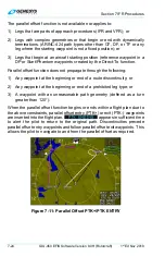
7.9. Parallel
Offsets
The parallel offset is a route parallel to, but offset from, the original active
route. The basis of the offset path is the original flight plan leg(s) and one
or more offset reference points as computed by the EFIS. The computed
offset reference points are located so they lie on the intersection of lines
drawn parallel to the host route at the desired offset distance and the line
that bisects the track change angle, except where the parallel offset ends.
In this case, the offset reference point is located abeam of the original flight
plan waypoint at the offset distance.