


Section 3 Display Symbology
1
st
Ed Nov 2018
IDU-450 EFIS Software Version 8.0H (Rotorcraft)
3-57
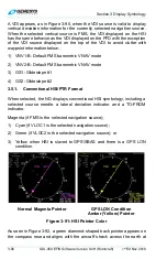
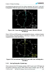
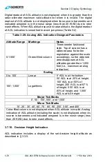
groundspeeds greater than 30 kts. When selected, the VLOC1, with GS1
is displayed. When the signal is invalid, the associated pointer is not shown.
Figure 3-92: Conventional HSI/PTR Format: HSI with VDI and
Glideslope
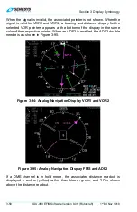
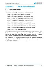
When VOR1 and VOR2 pointers are selected for display, a distance display
at the bottom of the ND appear. If bearing or distance is not valid, the
respective field is filled with dashes.
Figure 3-93: Conventional HSI/PTR Format with Loss of Navigation
Condition
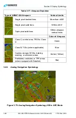
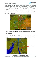
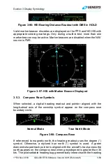
3.5.2. Analog
Navigation
Symbology
When selected, the HSI displays analog (VOR1 [cyan] and VOR2 [green])
navigation symbology with an RMI pointer format overlaid upon the HSI.