background image

Appendix B / Spare Parts

B - 1

Instrumentation and Pilot Air Spare Parts

(Choose the appropriate components pertaining to your dryer)

Local Mounted Moisture Indicator

Cat#

Description

1207278

Ind, Moisture; Repair Kit

Local Mounted Pressure Gauges

Cat#

Description

1125546

2-1/2 in, Brass, 0-200 PSIG, LOMTD

Pilot Filter Cartridges

Cat#

Description

1223259

AF2000-IR-20, For Housing NAF2000

Start-Up Valve

Cat#

Description

1274209

3-Way Poppet Valve

Filter Option Spare Parts

Drain Valve

Cat#

Description

1279674

Float Drain (for OM95-100PF & OM95-150PF)

1241814

GP250-115, 1/4 in

1245344

GP500-115, 1/2 in

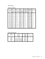
Filter Cartridges
(Choose the appropriate cartridge pertaining to your Filter Housing)

Dryer Model Number

Housing

Prefilter Cartridge Cat#

Afterfilter Cartridge Cat#

OP15, OP25

OM95-100PF/100AF

3014351

3014362

OP30

OM95-150PF/150AF

3014352

3014363

OP40, OP50, OP60

OM95-275PF/275AF

3014354

3014364

OP75

OM95-400PF/400AF

3014355

3014365

OP100, OP125

OM95-600PF/600AF

3014356

3014366

OP150

OM95-800PF/800AF

3014357

3014367

OP200

OM95-1000PF/1000AF

3014358

3014368

OP250

OM95-1200PF/1200AF

3014359

3014369

OP300

OM95-1600PF/1600AF

3014357

3014367

OP400

OM95-2000PF/2000AF

3014358

3014368

OP500

OM95-3000PF/2400AF

3014358

3014369

Note: Filter Housings OM95-100 through OM95-1200 require 1 Cartridge.

Filter Housings OM95-1600, OM95-2000 and OM2400 require 2 Cartridges.
Filter Housing OM95-3000 requires 3 Cartridges.

Appendix B

Spare Parts

Summary of Contents for Optima OP100

Page 1: ...Optima Series Regenerative Desiccant Dryer System Models OP15 through OP500 Installation Operation Maintenance Manual ...

Page 2: ... not be al lowed nor can we guarantee our equipment against corrosion or similar sources of failure where the operating conditions are beyond our control nor do we guarantee a minimum length of service on these products THE WARRANTY DESCRIBED ABOVE IS IN LIEU OF ALL WARRANTIES EXPRESS OR IMPLIED INCLUDING THE IMPLIED WARRANTY OF MERCHANTABILITY AND THE IM PLIED WARRANTY OF FITNESS FOR A PARTICULAR...

Page 3: ...2 2 Equipment Handling 2 1 2 3 Mechanical Set Up 2 1 2 4 General Piping Information 2 2 2 5 Purge Exhaust Restrictor 2 3 2 6 Purge Exhaust Muffler 2 3 2 7 Electrical Connection 2 3 2 8 Remote Alarm Connection 2 5 2 9 Equipment Check 2 5 2 10 Instrumentation 2 6 Section 3 Operation 3 1 Start Up 3 1 Dryer Models OP15 through OP200 3 1 Dryer Models OP250 and OP300 3 2 Dryer Models OP400 and OP500 3 4...

Page 4: ...0 4 10 4 9 2 Purge Exhaust Switching Valve Maintenance Model OP250 only 4 12 4 10 3 Purge Exhaust Switching Valve Maintenance Model OP300 only 4 14 4 11 1 Purge and Outlet Check Valve Maintenance Models OP15 through OP40 4 16 4 12 1 1 2 Purge and Outlet Check Valve Maintenance Models OP50 through OP75 4 18 4 13 2 Purge and Outlet Check Valve Maintenance Models OP100 through OP150 4 20 4 14 3 Purge...

Page 5: ...is designed to serve as the installation opera tion and maintenance guide for your dryer system The contents of this manual should be carefully read BEFORE attempting any phase of installation operation or mainte nance Failure to follow the operating and maintenance procedures of the instruction manual could result in per sonal injury or property damage To facilitate maintenance a Recommended Spar...

Page 6: ...odic draining 1 2 4 Afterfilter Assembly The General Pneumatics Particulate Afterfilter Assembly is another feature offered Even under the most ideal condi tions all regenerative type desiccant dryers tend to gener ate small quantities of micron sized desiccant dust par ticles This highly abrasive contaminant can erode instru ments valve seats air cylinders and pneumatic tools A General Pneumatics...

Page 7: ...the possibility of accidental damage if the unit is located in an open area or in close proximity to ve hicular and pedestrian traffic 2 1 Receiving and Inspection Immediately upon receipt of the dryer thoroughly inspect for damage that may have occurred during shipment Since the dryer is shipped F O B Ocala Florida the carrier is legally responsible for damage incurred during shipping Shipping da...

Page 8: ... all piping lengths and compo nents BEFORE installation Remove any inter nal oil water dirt or debris which may have accumulated during shipment and or storage NOTE 6 Leakage from piping connections and or asso ciated components installed upstream of the dryer will cause a loss of gas pressure and un necessary compressor cycling The slightest leakage from piping connections and or associ ated comp...

Page 9: ...dard equipment and therefore must be sup plied by the customer The dryer s electrical load is indicated on the Dryer Specification La bel located on the inside cover of the dryer con trol enclosure NOTE 4 The manufacturer is not liable for code viola tions component damage downtime or conse quential damages related to customer supplied and installed electrical components and con nections NOTE 5 Ex...

Page 10: ...T STRAP 3 MINIMIZE HANDLING 4 HANDLE STATIC SENSITIVE DEVICES BY THE BODY ONLY DO NOT TOUCH ANY CON NECTORS USE MICROCHIP EXTRACTION AND INSERTION TOOLS 5 KEEP PARTS IN ORIGINAL CONTAINERS UNTIL READY FOR USE 6 DO NOT SLIDE STATIC SENSITIVE DEVICE OVER ANY SURFACE 7 USE ANTISTATIC CONTAINERS FOR HANDLING AND TRANSPORT 8 KEEP PLASTIC VINYL AND POLYSTYRENE FOAM OUT OF THE WORK AREA 9 WHEN REMOVING A...

Page 11: ... during shipment can cause loosening of fit tings and fasteners Therefore inspect the dryer for alignment connection and tightness of all subassem blies etc 2 Remove shipping plugs from desiccant chamber fill ports 2 Apply TFE tape to threads and install relief valves 2 Note Pressure relief valves are offered as accesso ries and are shipped separately 3 On Models OP15 through OP300 desiccant is no...

Page 12: ...ure setting Moisture Indicator optional An indicator utilizing specially treated silica gel which changes color to alert personnel of a moisture problem re quiring corrective action The indicator is blue when dry but gradually changes to pink in color whenever a wet gas sample is received Valve Switching Failure optional This alarm is triggered when the drying chambers are not in the correct press...

Page 13: ...he dryer will not affect operation other than a slight loss of pressure supplied to the dryer HOWEVER any gas 3 1 Start Up WARNING Ensure that the dryer is de energized valve isolated and fully depressurized before attempting to remove or disassemble any dryer component or subassembly Failure to do so may result in serious personal injury and or equipment damage CAUTION Each component of a General...

Page 14: ...or dryers with the OPTITEK 2 EMS Energy Manage ment System During operation in the Energy Man agement Mode the off stream chamber may remain pressurized in ENERGY MANAGEMENT ACTIVE If this condition is noted proceed as follows to adjust purge pressure a Open Dryer Control System Enclosure Locate DIP switches on MEC CPU Board b Switch DIP switch position 7 to OFF position down De energize dryer s e...

Page 15: ...System Inlet Isolation Valve 6 Open customer supplied System Bypass Valve if in stalled 7 Close customer supplied System Outlet Isolation Valve 8 Supply compressed air up to Inlet Isolation Valve 9 Open the Pilot Gas Supply Valve located upstream of the Pilot Gas Filter 10 Supply pressure to system by slowly opening the Sys tem Inlet Isolation Valve customer supplied The Inlet Switching Valve will...

Page 16: ...at supply pressure open the Pilot Gas Supply Valve and disconnect the gas supply to the pilot gas system at the Start Up Ball Valve 12 The Moisture Indicator s if dryer so equipped bleed valve is installed directly into the back of the indicator s body Close the Indicator s Bleed Valve FULLY open the Moisture Indicator Supply Valve 13 Soap bubble test all external piping fittings and con nections ...

Page 17: ...d 5a The dryer s microprocessor control should automati cally switch the system from left to right and right to left chamber drying on a fixed time cycle If the sys tem fails to switch drying chambers twice within its designated NEMA Cycle refer to the TROUBLE SHOOTING GUIDE 5b If an OPTITEK 2 Energy Management System Con trol indicates a High Humidity Warning upon start up it should automatically...

Page 18: ...tions WARNING Ensure that the system is de energized valve iso lated and fully depressurized before attempting to remove or disassemble any component or sub assembly Failure to do so may result in serious personal injury and or equipment damage 6 To depressurize dryer proceed as follows a Open customer supplied System Bypass Valve if gas system has been so equipped b Close the Pilot Gas Supply Val...

Page 19: ...liquid and oil carry over from the prefilter due to a clogged or inoperative automatic drain valve Quarterly Check the dry gas outlet dew point A precision Dew Point Analyzer is required to read the exact dew point The ana lyzer should be connected as close to the dryer outlet as is possible Test piping or tubing used to connect the ana lyzer to the gas system must be metallic as rubber and certai...

Page 20: ...cy or damage the Dryer CAUTION Prior to installing desiccant review all appli cable Material Safety Data Sheets and container warnings Safety Data Sheets may be obtained from the manufactur ers Safety Coordinator Exercise all necessary precau tions for your health and welfare WARNING A static electric charge can build up when pouring desiccants or dry powders Proper grounding should be observed wh...

Page 21: ...ate afterfilters are in cluded with all Optima Series Dryers The filter elements should be replaced when the differential pressure gauge on top of the filter reads 7 to 10 psid or once a year whichever comes first Refer to Appendix B for the re placement element part numbers Replace elements in accordance with the following instructions Dryer Models OP15 through OP250 WARNING Ensure that the Dryer...

Page 22: ...manual and automatic drain valves if installed 4 Remove the bolts securing the filter cover to the ves sel 5 Remove the filter cover 6 Unscrew and remove cartridge retaining seal nuts 7 Remove the used element cartridges Discard the cartridges in accordance with applicable regulations Used elements typically hold contaminants such as compressor lubricants and particulate matter 8 Insert new elemen...

Page 23: ...ervice valve 13 Slowly open the inlet isolation valve to prevent a pres sure surge through the filter 14 Once the filter has been pressurized slowly open the outlet isolation valve 15 After both isolation valves have been opened close the system bypass valve The filter is now in service 4 5 Automatic Drain Valve Disassembly and Servicing Dryer models OP40 and larger have a timer controlled au toma...

Page 24: ...wing main tenance can be performed 1 Inspect diaphragm clean or replace as required 2 Remove debris from the valve body 3 Wipe solenoid core components with a clean cloth or blow out debris with compressed air from an OSHA approved air nozzle that limits the discharge pressure to 30 psig 4 Check the small port in diaphragm assembly is clear and solenoid coil moves freely in housing Viton dia phrag...

Page 25: ...nd 9 from body 8 by turning screw 6 counter clockwise 3 Remove screw 6 from sight dome 2 by exerting pressure on screw s threaded end Drain granular indicator 4 Remove porous disc 4 and clean sight dome see following CAUTION CAUTION Sight Dome 2 is an acrylic plastic Do Not clean with any type of solvent 5 Replace O ring 9 and re install screw 6 in sight dome 2 6 Carefully pour new granular indica...

Page 26: ...ston seal is installed on the valve pistons 4 and 5 as shown in Figure 4 3 5 Apply a light coat of lubricant to the sockethead cap screws items 1 and 18 Hand tighten screws until snug Torque as follows Torque 1 4 20 screws to 40 in lbs Torque 5 16 18 screws to 135 in lbs Switching Valve Components Item Description Total 1 Valve Body 1 2 Valve Cover Left Side 1 3 Valve Cover Right Side 1 4 Valve Pi...

Page 27: ...igure 4 4 INLET AND PURGE EXHAUST SWITCHING VALVE OP15 OP25 OP30 OP40 OP50 OP60 OP75 OP100 OP125 OP150 OP200 NOTE 1 When the unit is located in a corrosive environment coat sockethead cap screws with a corrosion resistant compound ...

Page 28: ...ted inside the valve body 21 As previously noted this can be accom plished without removing the valve body 9 from the dryer manifold 3 Apply an ultra thin film of O ring lubricant to items 3 6 8 12 14 and 23 before reassembly 4 Apply a light coat of lubricant to the sockethead cap screws items 1 20 and 22 Hand tighten screws until snug Torque items 1 and 20 to 20 ft lbs and item 22 to 45 ft lbs 3 ...

Page 29: ...Maintenance and Repair 4 11 Figure 4 5 3 INLET SWITCHING VALVE OP250 OP300 NOTE 1 When the unit is located in a corrosive environment coat sockethead cap screws with a corrosion resistant compound ...

Page 30: ...the valve body 16 As previously noted this can be accom plished without removing the valve body 16 from the dryer manifold 3 Apply an ultra thin film of O ring lubricant to items 3 5 8 11 and 17 before reassembly Do not ap ply lubricant to the valve seat seal 13 4 The U cup piston seal 5 has been fitted with a cut O ring Ensure that the U cup piston seal is installed on the valve piston 4 as shown...

Page 31: ...Maintenance and Repair 4 13 Figure 4 6 2 PURGE EXHAUST OP250 NOTE 1 When the unit is located in a corrosive environment coat sockethead cap screws with a corrosion resistant compound ...

Page 32: ... software and any hardware which ap pears damaged or abnormally worn 2 Clean and inspect valve seat located inside the valve body 18 As previously noted this can be accom plished without removing the valve body 18 from the dryer manifold 3 Apply an ultra thin film of O ring lubricant to items 3 6 8 12 14 and 19 before reassembly 4 Apply a light coat of lubricant to the sockethead cap screws items ...

Page 33: ...Maintenance and Repair 4 15 Figure 4 7 3 PURGE EXHAUST SWITCHING VALVE OP300 NOTE 1 When the unit is located in a corrosive environment coat sockethead cap screws with a corrosion resistant compound ...

Page 34: ... and inspect all valve hardware upon disassem bly Replace all software and any hardware which ap pears damaged or abnormally worn Closely inspect valve poppets 23 check balls 8 purge adjusting valve 12 and associated mating sealing surfaces for any faults which could prevent positive sealing 2 Apply an ultra thin film of O ring lubricant to items 6 7 10 11 16 17 and 22 Do not apply lubri cant to c...

Page 35: ...RGE AND OUTLET CHECK VALVE ASSEMBLIES OP15 OP25 OP30 OP40 NOTE 1 When the unit is located in a corrosive environment coat items 2 and 3 with a corrosion resistant com pound 2 Torque 1 4 20 screws to 40 in lbs Torque 5 16 18 screws to 135 in lbs ...

Page 36: ...lacement 1 Clean and inspect all valve hardware upon disassem bly Replace all software and any hardware which ap pears damaged or abnormally worn Closely inspect valve poppets 21 check balls 8 purge adjusting valve 12 and associated mating sealing surfaces for any faults which could prevent positive sealing 2 Apply an ultra thin film of O ring lubricant to items 6 7 10 11 16 17 and 20 Do not apply...

Page 37: ... 2 PURGE AND OUTLET CHECK VALVE ASSEMBLIES OP50 OP60 OP75 NOTE 1 When the unit is located in a corrosive environment coat items 2 and 3 with a corrosion resistant com pound 2 Torque 1 4 20 screws to 40 in lbs Torque 5 16 18 screws to 135 in lbs ...

Page 38: ...sitates replacement 1 Clean and inspect all valve hardware upon disassem bly Replace all software and any hardware which ap pears damaged or abnormally worn Closely inspect valve poppets 7 check balls 15 purge adjusting valve 6 and associated mating sealing surfaces for any faults which could prevent positive sealing 2 Apply an ultra thin film of O ring lubricant to items 10 11 12 17 and 18 Do not...

Page 39: ...URGE AND OUTLET CHECK VALVE ASSEMBLIES OP100 OP125 OP150 NOTE 1 When the unit is located in a corrosive environment coat items 13 and 14 with a corrosion resistant compound 2 Torque 5 16 18 screws to 135 in lbs Torque 3 8 16 screws to 245 in lbs ...

Page 40: ...sitates replacement 1 Clean and inspect all valve hardware upon disassem bly Replace all software and any hardware which ap pears damaged or abnormally worn Closely inspect valve poppets 7 check balls 15 purge adjusting valve 6 and associated mating sealing surfaces for any faults which could prevent positive sealing 2 Apply an ultra thin film of O ring lubricant to items 10 11 12 17 and 18 Do not...

Page 41: ...URGE AND OUTLET CHECK VALVE ASSEMBLIES OP200 OP250 OP300 NOTE 1 When the unit is located in a corrosive environment coat items 13 and 14 with a corrosion resistant compound 2 Torque 5 16 18 screws to 135 in lbs Torque 3 8 16 screws to 245 in lbs ...

Page 42: ...qually loosening flange bolts Ensure that the method of support is prepared to accept the muffler and flow restrictor s full weight when the last bolt is re moved see following CAUTION CAUTION Exercise caution when lowering muf fler and flow restrictor to prevent damaging control tubing and the Purge Pressure Indicator 2 Remove clean and inspect the spring and orifice type flow restrictor Install ...

Page 43: ... of the assembly If a tendency to bind erratic operation damage and or excessive wear is noted disassemble and repair the assembly DISASSEMBLY ASSEMBLY INSTRUCTIONS 1 Disassemble Build the flow restrictor assembly in the order shown by the Flow Restrictor Assembly Diagram Figure 4 14 A Hand tighten studs in sequence shown in Detail A B Tighten studs in sequence shown to 30 ft lbs torque C Leak che...

Page 44: ...ly 80 100 lbs force Note Loctite RC 620 must be applied to the shaft guide to prevent loosening during operation C Tighten cap screws to 4 5 lbs torque D Lockwire cap screws as shown in Detail B Note Correctly applied lockwire will tend to tighten both cap screws ACTUATOR SUBASSEMBLY Item Description Total 2A Valve Flange 1 2B Shaft Subassembly 1 2C Spacer 4 2D Mounting Plate 1 2E Vibration Pad 1 ...

Page 45: ... Continue tightening nut for an additional 1 2 turn E Remove subassembly from the vice Install the cotter pin Note Orifice stroke adjustment is critical to the opera tion of the flow restrictor DISASSEMBLY ASSEMBLY INSTRUCTIONS SHAFT SUBASSEMBLY 1 Disassemble Build the shaft subassembly in the order shown by the Shaft Subassembly Diagram Figure 4 16 2 Preload the orifice spring A Tighten nut until...

Page 46: ...serious personal injury and or equipment damage Note Removal of valve body 4 is not required unless replacement of valve body is necessary 1 Clean and inspect all valve hardware upon disassembly Replace all software and any hardware which appears damaged or abnormally worn 2 Apply an ultra thin film of O ring lubricant to item 2 before reassembly Item Description Quantity 1 Retaining Ring 1 2 O ri...

Page 47: ...ough filter assembly is from outside of filter cartridge to the inside center 1 Clean and inspect all hardware upon disassembly Replace filter cartridge software and any hardware which appears damaged or abnormally worn 2 Apply an ultra thin film of O ring lubricant to filter cartridge s O ring and O ring 2 3 Close filter bleed valve 6 following reassembly Item Description Quantity 1 Head Assembly...

Page 48: ......

Page 49: ...t damage WARNING Some of the following troubleshooting checks require entering the Dryer Control System enclosure while the Dryer s Electrical Power Supply is energized THEREFORE A POTENTIAL ELECTRICAL SHOCK HAZARD EXISTS These checks should be conducted by a qualified electrical technician or a General Pneumatics authorized field service engineer ONLY The Dryer s Electrical Power Supply must be d...

Page 50: ...dicator s bleed valve as instructed in previous step 1 3 Refer to Moisture Indicator Recharging Procedure section of this manual for disassembly instructions Clean or replace components as necessary 4 Perform a soap bubble leak test on indicator s tubing and fit tings Tighten or repair all noted points of leakage 5 Refer to dew point degradation section of this Troubleshoot ing Guide Determine and...

Page 51: ...tem s power fuse F1 is blown 4 Damaged components 1 SLOWLY rotate Purge Adjusting Valve until correct purge pres sure setting is noted on the Purge Pressure Indicator Note The purge pressure setting can only be read and ad justed when the off stream chamber has depressurized for re generation When the off stream chamber is pressurized the Purge Pressure Indicator will read system pressure 2 Shutdo...

Page 52: ...screens through fill and drain ports and clean if fouling is noted Investigate and remedy source of fouling CAUTION Desiccant may be reinstalled if it is not fouled or badly broken 4 Shutdown and Depressurize Dryer Replace damaged faulty or out of calibration gauges 1 Shutdown and Depressurize Dryer Proceed as follows a For Model OP250 only 1 Provide adequate support for muffler and flow restricto...

Page 53: ...anically the solenoid valve coil is defective Replace solenoid valve coil Note The dryer MUST be depressurized to change coils on a solenoid b If voltage is present and the inlet valve doesn t open mod els OP15 through OP300 or close models OP400 and OP500 when overriding the solenoid valve the solenoid valve is defective Replace solenoid valve c If voltage is not present replace MEC Board 3 Shutd...

Page 54: ...echanically the purge exhaust valve should open the solenoid valve coil is defective Replace solenoid valve coil Note The dryer MUST be depressurized to change coils on a solenoid b If voltage is present and the purge exhaust valve doesn t open when manual overriding the solenoid valve the sole noid valve is defective Replace solenoid valve c If voltage is not present replace MEC Board 1 Shutdown ...

Page 55: ...e dryer s de sign inlet flow rate as specified on the Dryer Specification Label located on the inside cover of the dryer system control enclosure Excessive flow rates will result in excessive moisture loading of the desiccant beds This overload condition would raise the Optitek Sensor s moisture related frequency signal above the microcomputer s compara tor set point range and therefore would be i...

Page 56: ...Clean ports 1 Check and correct power supply and connections 2 Replace timer assembly Automatic drain valve continually discharging or venting 1 Clogged diaphragm 2 Short in electrical component Automatic drain valve not discharging 1 No electrical power 2 Timer malfunction 3 Solenoid coil malfunction 4 Clogged ports No response when push to test button on auto matic drain valve is pressed 1 No el...

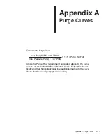
Page 57: ...SIG 1 15 Purge SCFM Inlet Pressure PSIG 14 7 PSIG Cross the Purge Flow requirement calculated above to the same number on the Critical Orifice Calibration Curve Follow this line ver tically and then horizontally once intersection is made with the curve line to find the actual purge pressure setting ...

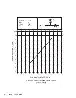
Page 58: ...A 2 Appendix A Purge Curves CRITICAL ORIFICE CALIBRATION CURVE OP15 Orifice Dia 156 Gas Air Temp 100 F CD 65 ...

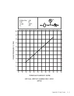
Page 59: ...Appendix A Purge Curves A 3 CRITICAL ORIFICE CALIBRATION CURVE OP25 Orifice Dia 219 Gas Air Temp 100 F CD 65 ...

Page 60: ...A 4 Appendix A Purge Curves CRITICAL ORIFICE CALIBRATION CURVE OP30 OP40 Orifice Dia 250 Gas Air Temp 100 F CD 65 ...

Page 61: ...Appendix A Purge Curves A 5 CRITICAL ORIFICE CALIBRATION CURVE OP50 Orifice Dia 281 Gas Air Temp 100 F CD 65 ...

Page 62: ...A 6 Appendix A Purge Curves CRITICAL ORIFICE CALIBRATION CURVE OP60 OP75 Orifice Dia 375 Gas Air Temp 100 F CD 65 ...

Page 63: ...Appendix A Purge Curves A 7 CRITICAL ORIFICE CALIBRATION CURVE OP100 Orifice Dia 406 Gas Air Temp 100 F CD 65 ...

Page 64: ...A 8 Appendix A Purge Curves CRITICAL ORIFICE CALIBRATION CURVE OP125 OP150 Orifice Dia 500 Gas Air Temp 100 F CD 65 ...

Page 65: ...Appendix A Purge Curves A 9 CRITICAL ORIFICE CALIBRATION CURVE OP200 Orifice Dia 563 Gas Air Temp 100 F CD 65 ...

Page 66: ...A 10 Appendix A Purge Curves CRITICAL ORIFICE CALIBRATION CURVE OP250 OP300 Orifice Dia 688 Gas Air Temp 100 F CD 65 ...

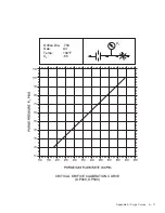
Page 67: ...Appendix A Purge Curves A 11 CRITICAL ORIFICE CALIBRATION CURVE OP400 OP500 Orifice Dia 750 Gas Air Temp 100 F CD 65 ...

Page 68: ......

Page 69: ...hoose the appropriate cartridge pertaining to your Filter Housing Dryer Model Number Housing Prefilter Cartridge Cat Afterfilter Cartridge Cat OP15 OP25 OM95 100PF 100AF 3014351 3014362 OP30 OM95 150PF 150AF 3014352 3014363 OP40 OP50 OP60 OM95 275PF 275AF 3014354 3014364 OP75 OM95 400PF 400AF 3014355 3014365 OP100 OP125 OM95 600PF 600AF 3014356 3014366 OP150 OM95 800PF 800AF 3014357 3014367 OP200 ...

Page 70: ...t Valve Repair Kit 1256409 1 Purge Valve Repair Kit 1256414 1 OP100 Inlet Exhaust Valve Pkg Kit 1272494 1 Outlet Purge Chk Valve Pkg Kit 1256400 1 Inlet Exhaust Valve Repair Kit 1272486 1 Outlet Valve Repair Kit 1256411 1 Purge Valve Repair Kit 1256415 1 OP125 Inlet Exhaust Valve Pkg Kit 1272495 1 Outlet Purge Chk Valve Pkg Kit 1256400 1 Inlet Exhaust Valve Repair Kit 1272487 1 Outlet Valve Repair...

Page 71: ...e Repair Kit 1256413 1 Purge Valve Repair Kit 1256415 1 Flow Restrictor Repair Kit 1205911 1 Flow Restrictor Rebuild Kit 1205937 1 OP400 Inlet Valve Pkg Kit 1252986 2 Exhaust Valve Pkg Kit 1252986 2 Flow Restrictor Repair Kit 1205911 1 Flow Restrictor Rebuild Kit 1205937 1 OP500 Inlet Valve Pkg Kit 1252985 2 Exhaust Valve Pkg Kit 1252986 2 Flow Restrictor Repair Kit 1205911 1 Flow Restrictor Rebui...

Page 72: ...4 lbs 4 1269705 OPD 4 150 150 lbs 1 OP75 1269704 OPD 4 34 S 34 lbs 4 1269705 OPD 4 150 150 lbs 1 OP100 1269704 OPD 4 34 S 34 lbs 1 1269706 OPD 4 350 350 lbs 1 OP125 1269704 OPD 4 34 S 34 lbs 1 1269705 OPD 4 150 150 lbs 3 OP150 1269704 OPD 4 34 S 34 lbs 1 1269705 OPD 4 150 150 lbs 2 1269706 OPD 4 350 350 lbs 1 OP200 1269705 OPD 4 150 150 lbs 1 1269706 OPD 4 350 350 lbs 2 OP250 1269704 OPD 4 34 S 34...

Page 73: ... 375 27 1198374 1 OP100 504 76 0 406 35 1198415 2 OP125 630 95 0 500 27 1183532 2 OP150 760 114 0 500 35 1183532 2 OP200 1000 150 0 563 37 1183533 2 OP250 1250 186 0 688 28 1210703 2 OP300 1500 225 0 688 37 1210703 2 OP400 2070 311 0 750 46 1268843 1 OP500 2850 430 0 750 69 1268843 1 Purge Flow Details Spare Orifices Dump Orifice Details Model Orifice Assembly Number Diameter Catalog Quantity inch...

Page 74: ...76724 Solenoid Valve Coil 5 1261094 Power Supply 1 1274958 PCB Assy Hazardous Location 1 1177244 Fuse Hazardous Location 1 1222747 Relay Hazardous Location 1 Optional Electrical Components Cat Description Qty Per Dryer 1260773 Optitek Humidity Sensor 1 1271486 Optitek PC Board 1 1221910 Pressure Switch 2 1262602 Pressure Switch Cable Assy 2 ...

Reviews: