Maintenance and Repair
4 - 25
4.16
Flow Restrictor Maintenance
(Models OP300 through OP500)
WARNING!
Ensure that the dryer and any associated prefilters
and afterfilters are valve isolated and fully depressur-
ized before attempting to remove or disassemble any
components or subassemblies. Failure to do so may
result in serious personal injury and/or equipment
damage.
1.
Clean and inspect the assembly. Check operation of
the assembly. If a tendency to bind, erratic operation,
damage and/or excessive wear is noted, disassemble
and repair the assembly.
DISASSEMBLY/ASSEMBLY INSTRUCTIONS
1.
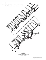
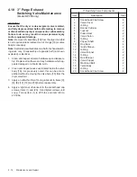
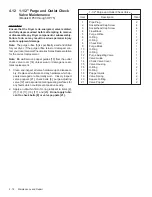
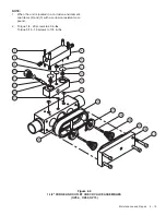
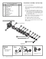
Disassemble/Build the flow restrictor assembly in the
order shown by the Flow Restrictor Assembly Diagram
(Figure 4.14).
A) Hand tighten studs in sequence shown in Detail A.
B) Tighten studs in sequence shown to 30 ft-lbs.
torque.
C) Leak check valve.
FLOW RESTRICTOR ASSEMBLY
FLOW RESTRICTOR ASSEMBLY
Item
Description
Total
1
Valve Body
1
2
Actuator Subassembly
1
3
Valve Flange
1
4
O-Ring
2
5
Hex Nut
8
6
Threaded Stud
4
DETAIL 'A'
Figure 4.13
Figure 4.14

