


www.gemu-group.com
16 / 33
GEMÜ 1441 cPos-X
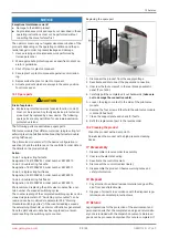
8 Montage
7
6
4
3
1
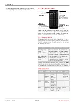
1. Mount the travel sensor mounting kit (see “Mounting kit
assembly (quarter turn actuator) for remote mounting“,
2. Place the travel sensor
7
with adapter
4
and mounting
bracket
6
on the actuator
3
.
ð
Note:
The adapter lug 4 must engage in the actuator
shaft groove.
3. Mount the mounting bracket
6
on the actuator
3
using the
screws, washers and spring washers provided.
NOTICE
Note for the rotary travel sensor
▶
The slotted holes should be positioned in the centre on
the screws. If the travel range is incorrect, (determined by
checking the attachment), loosen the two screws slightly
and twist the travel sensor. Set the travel up correctly and
tighten the screws again.
4. Secure the product
1
in a suitable position.
5. The product offers two options for securing:
ð
Four fixing holes with threaded sleeves are located on
the rear of the housing, using which the controller can
be installed on holders/routes, etc.
ð
An attachment point for a mounting bracket is located
on the underside of the housing. Two different variants
are available as accessories for this. Depending on the
desired version, the product can therefore be mounted
on level surfaces or on walls.
NOTICE
Mounting bracket for wall mounting
▶
The GEMÜ 1441 000 ZMP mounting bracket, which is
available separately, can be used for this.
NOTICE
Mounting bracket for mounting on level surfaces
▶
The GEMÜ 1441 000 ZMB mounting bracket, which is
available separately, can be used for this.
6. Electrically connect the travel sensor to the product.
7. Connect the product's pneumatic supply and connect the
product to the process valve.
8.12 Checking the mechanical mounting
1. Connect the product electrically (see “Electrical connec-
2. Connect the product pneumatically.
3. The display shows
"Starting…"
for approx. 20 seconds and
then the following information:
4. The mounted actuator can be moved to the OPEN and
CLOSED positions using the app connectivity. Alternat-
ively, the valve actuator can be moved to the other end po-
sition by applying direct pressure on the compressed air
connection.
5.
Important
: In this case, the displayed valve position
("POS") must be between 2% and 98%. If the display exits
this area, check the mechanical mounting again (check
the compatibility of the mounting parts) and, if required,
readjust the direction of the rotary travel sensor.


